MkaPEB Pre-Engineered Building (PEB)
MkaPEB is the most efficient and comprehensive software ever developed for the analysis and design of single-storey steel structures worldwide.
It empowers engineers to achieve the most cost-effective solutions in the shortest time, all while maintaining the highest standards of quality.
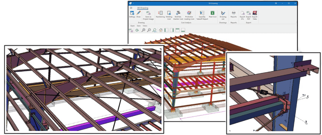
Table of Contents
1-Definition and fundamental concepts of PEBs
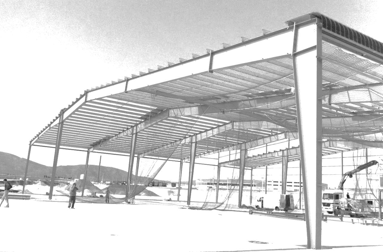
A Pre-Engineered Building (PEB) is a type of construction system where the building components are designed, engineered, and fabricated in a controlled factory environment, and then assembled on site. Unlike traditional construction methods that rely on extensive on-site work, PEBs are built using prefabricated steel structures tailored to the exact requirements of a project.
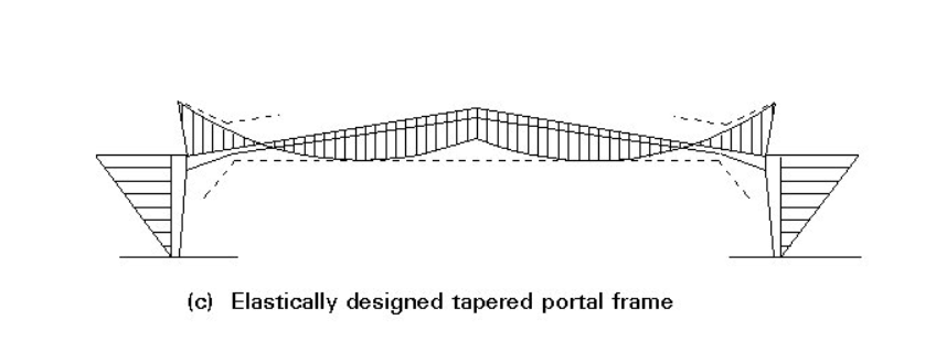
The core concept of PEB design is to shape the frame geometry according to the bending moment diagram, allowing for optimized material use by varying section sizes along the members—unlike Conventional Steel Buildings (CSBs), which typically use uniform sections throughout, even where less strength is needed, resulting in unnecessary material use.
2-Comparison of PEB with CSB
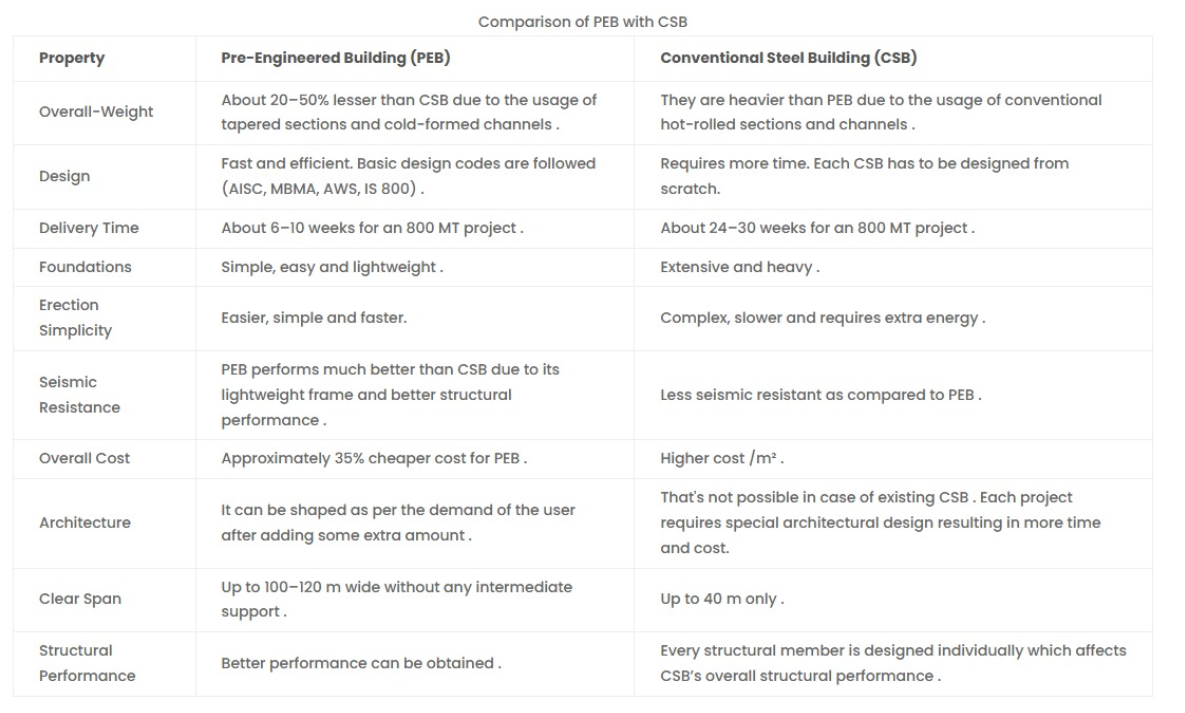
Major differences between Pre-Engineered Buildings (PEBs) and Conventional Steel Buildings (CSBs) are tabulated bellow:
REF: https://doi.org/10.1016/j.matpr.2022.11.361
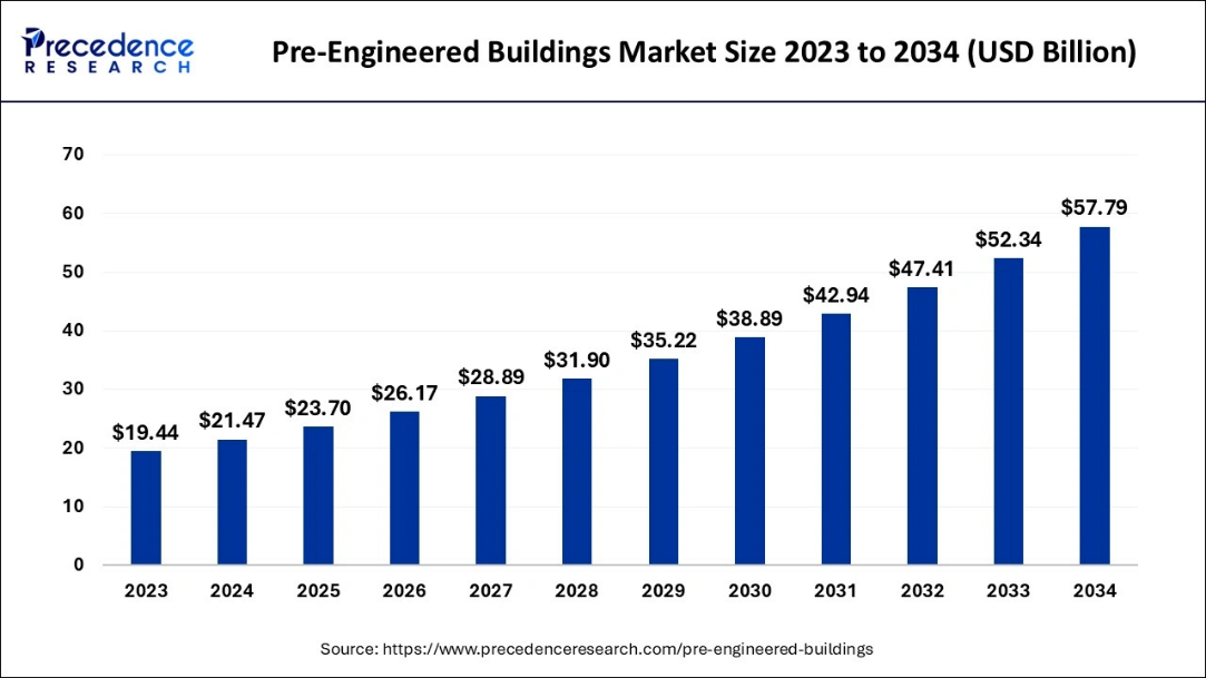
3-PEBs Market Size and Forecast 2023 to 2034
Pre-engineered buildings gained popularity during WWII when the US Army utilized them as aircraft hangars and temporary barracks. By the year 2000 over 80% of all non-residential single-story buildings in the USA were being constructed using PEB system. Nowadays, due to its advantages such as design flexibility, adaptability, recyclability, and low cost, this system is used in the construction of different structures such as warehouses, factories, offices, workshops, malls, gas stations, aircraft hangars, etc. around the world.

4-Common Frame Configurations in PEBs
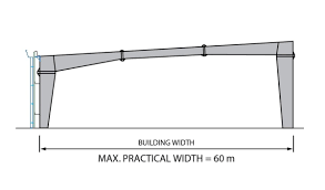
Pre-Engineered Buildings can be configured in various structural frame types to meet specific functional, architectural, and load-bearing requirements. Each profile offers unique benefits depending on span width, interior space needs, and cost considerations. Below are some of the most widely used frame profiles:
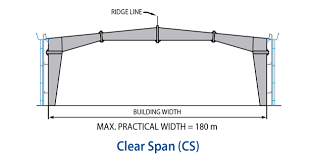
4.1 Clear Span (CS) Frame
The Clear Span frame is a structural system that spans the entire building width without any intermediate columns. This configuration is ideal for applications requiring unobstructed interior space, such as aircraft hangars, sports arenas, Warehouses, or manufacturing plants with large equipment.
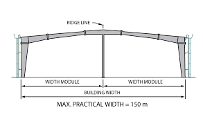
4.2 Multi-Span (MS) Frame
The multi-span frame features one or more interior columns that divide the building span into multiple bays. This allows for longer overall building widths while using smaller individual structural members, reducing material costs. This frame type is commonly used in large factories, storage facilities, and logistics hubs.
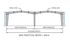
4.3 Multi-Gable (MG) Frame
The multi-gable frame combines multiple ridges and valleys within the same structure, giving the roofline a series of peaks. This design offers both aesthetic appeal and functional segmentation of interior spaces and can improve drainage and ventilation. This configuration is ideal for commercial buildings, shopping centers, institutional structures
4.4 Single Slope (SS) Frame
The Single Slope frame has a roof that slopes in one direction, typically used when drainage, sun orientation, or aesthetic considerations are critical. It’s also useful in buildings adjacent to other structures or in phased expansions. Typical Uses of the frames are in warehouses, sheds, retail outlets, extensions to existing buildings.
5-The composition of PEBs
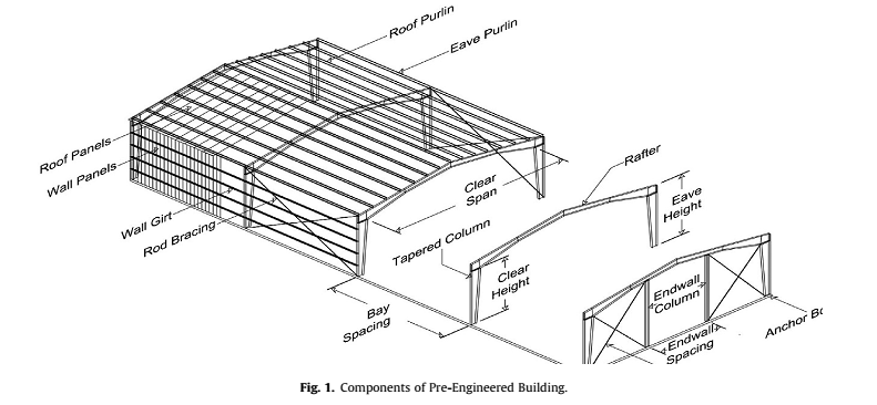
Below is a full overview of the main components of the PEB structures:
Primary structural members: PEB's main stiff frame is made up of I shaped members that are tapered or built up with hot-rolled plates. Columns are vertical members, while rafters are horizontal members.
Secondary structural members: Z and C shaped cold-formed structural members include purlins for the roof, eave struts, and wall girts. Cold formed members do not require cutting, welding, or grinding because they are created directly by pressing the steel coil in a pressing machine to get the desired shape.
Sheeting/cladding: It includes roll-formed profiled sheeting for the roof and walls. These are color-coated, galvalume, or galvanized steel ribbed panels.
Miscellaneous: It comprises functional components such as mezzanine flooring for intermediate levels, crane runway beams for crane systems, sag rods to limit purlin and girt movement in the direction of their weak axis, anchor bolts to attach parts to the foundation or other support structures, and strut pipes.
Accessories include aesthetic components such as fascia to improve wall appearance, canopy as an overhanging roof structure, louvers as slanted wall openings to facilitate air flow, parapet, roof extensions, skylight, and turbo vent.

Ref: https://doi.org/10.1016/j.matpr.2022.11.361
6-Detailed Breakdown of PEB Elements
6.1. BRACING
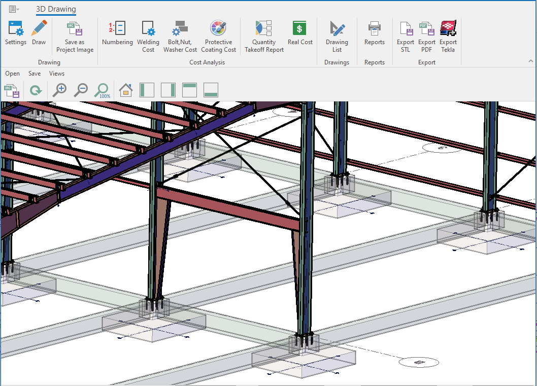
Bracing refers to a system of structural elements—typically steel rods, angles, or cables—installed within the framework of a building to provide stability and strength against horizontal forces. In a Pre-Engineered Building (PEB), bracing is a crucial part of the design, often forming an invisible but vital network of support that ensures the structure maintains its shape and integrity during various loading conditions.
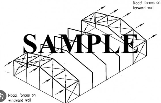
Bracing is typically installed in strategic locations throughout the building:
• Roof Bracing: Helps maintain the roof’s shape and distributes wind and seismic forces to the walls and foundation.
• Wall Bracing (Side and End Walls): Controls lateral movement and stabilizes the vertical plane of the building.
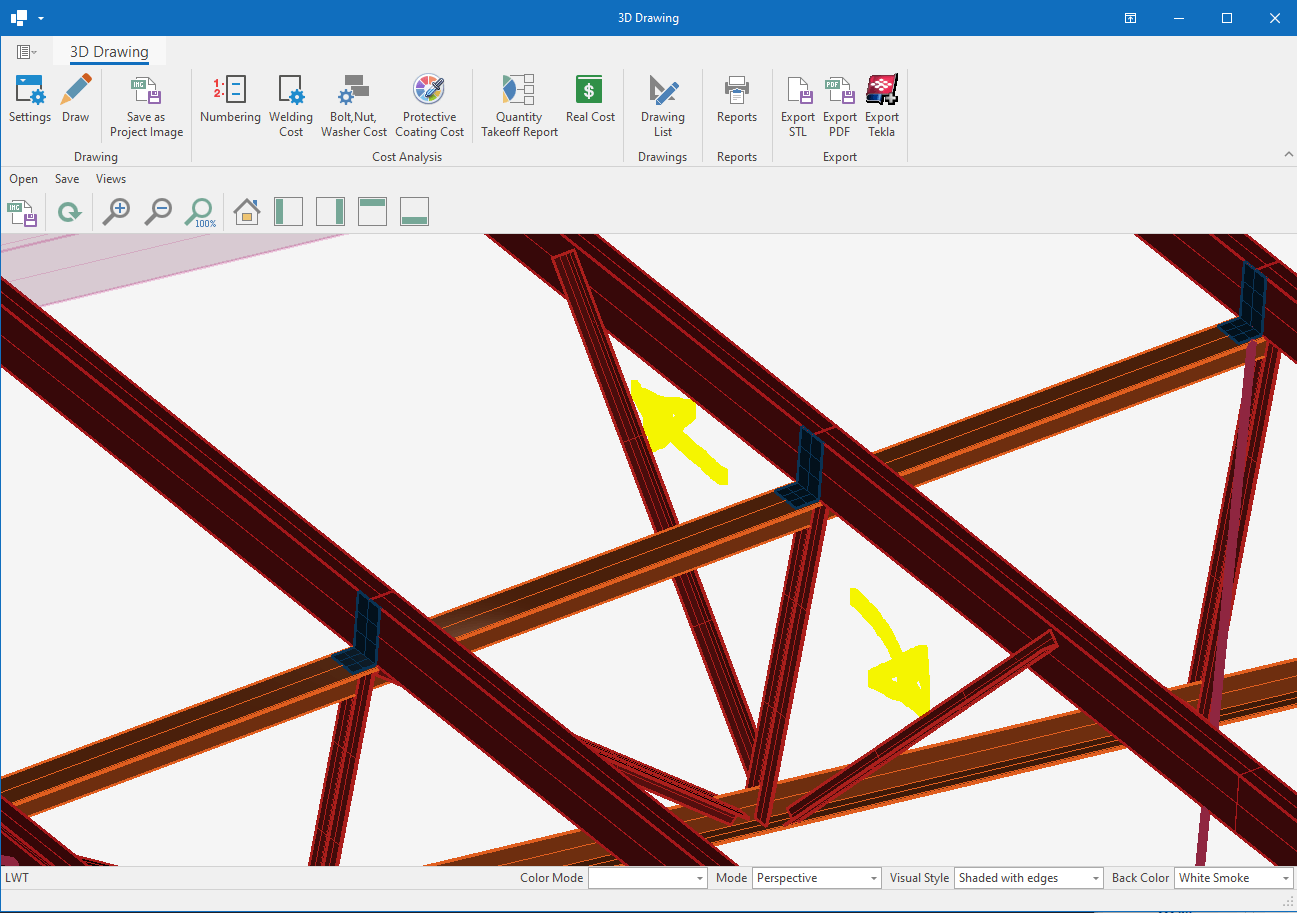
Bracing systems are critical for the overall stability and performance of a Pre-Engineered Building. Here’s why:
Resisting Lateral Loads
One of the primary purposes of bracing is to resist lateral forces that can cause a building to sway or distort. Wind loads, seismic events, or unbalanced equipment movement can exert sideways pressure that, if unresisted, could cause structural failure.
Maintaining Building Shape (Geometry Control)
Bracing acts like a skeleton that keeps the building square and plumb. It prevents deformation or twisting of the structure under load, helping maintain the original geometry during construction and service life.
Reducing Frame Stress
Properly designed bracing reduces the lateral forces that would otherwise be transferred entirely to the primary structural frames. This leads to smaller section sizes, cost savings, and improved safety.
Supporting Crane Systems and Heavy Equipment
In buildings that include overhead cranes or heavy machinery, bracing provides the necessary lateral stiffness to absorb the additional dynamic forces produced during operation.
Improving Structural Redundancy
Bracing adds an extra layer of safety. In the event of localized frame damage, bracing helps redistribute loads and delays progressive collapse.
When designing bracing systems, engineers consider several factors:
• Wind and seismic loads based on location
• Building height, width, and span
• Presence of openings (doors, windows) that limit bracing placement
• Architectural constraints or aesthetic requirements
• Ease of construction and material availability
Bracing must be efficient, cost-effective, and compatible with other building systems. In some cases, bracing can also be architecturally exposed, serving both structural and aesthetic purposes.
6.2. PURLIN
Purlins are horizontal structural members used in the roof system of Pre-Engineered Buildings (PEBs). They span between the building’s main rafters or frames and serve as the support framework for roof panels or sheets. Purlins play a vital role in distributing roof loads and providing a stable platform for cladding installation. Typically made from cold-formed steel, purlins are lightweight yet strong, and they are a key element in achieving the long, clear spans that make PEBs so efficient.
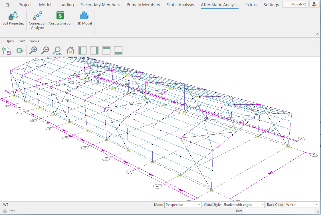
Purlins are the direct support system for the roof sheeting. They carry the weight of the roofing material, along with any superimposed loads such as snow, wind, or equipment. They transfer loads from the roofing sheets to the primary rafters, ensuring the building can withstand environmental and service-related forces without excess stress on individual components. By acting as intermediate supports, purlins reduce the span that roof sheets must cover, which means lighter, more economical materials can be used without compromising strength. Purlins also enhance the lateral stability of the roof system, helping maintain the shape and alignment of the rafters and preventing buckling.
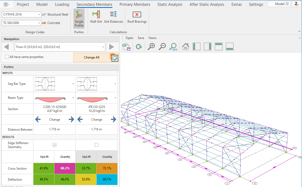
When designing purlins for a PEB roof, engineers must consider:
• Roof slope and span
• Live and dead loads, including wind uplift
• Spacing between primary frames
• Deflection limits for performance and safety
• Corrosion resistance, especially in humid or corrosive environments
The optimal purlin design ensures strong, lightweight, and cost-efficient roofing, which is one of the key advantages of using PEB systems.
6.3 FLANGE BRACINGS
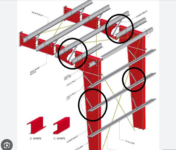
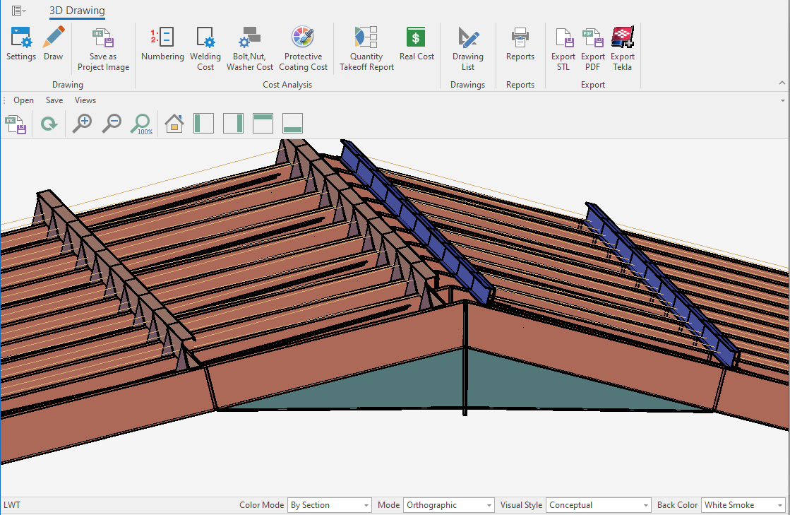
Flange bracing is a system of secondary members or stabilizing elements used to restrain the compression flanges of primary structural elements—such as rafters and columns—against lateral displacement and torsional (twisting) instability. In the context of Pre-Engineered Buildings (PEBs), where tapered, lightweight, high-strength steel members are used, flange bracing is critical for ensuring structural safety and efficiency.
When a structural member such as a rafter or column is loaded, the flange under compression tends to buckle laterally if not properly braced. Flange bracing acts like a "support hand" to hold this flange in position, increasing the member’s buckling capacity and allowing it to carry more load using less material.
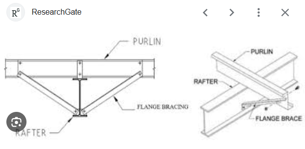
6.3.1. Flange Bracing Functions:
Prevents Lateral-Torsional Buckling (LTB)
Flange bracing stabilizes the compression flange, which is susceptible to buckling out of its plane. Without bracing, the member may fail at much lower loads due to LTB.
Increases Load-Carrying Capacity
Braced members can carry significantly higher bending moments than unbraced ones, making them structurally efficient and economically optimized.
Enables Tapered Member Design
PEBs often use tapered I-sections that are slender and more prone to instability. Flange bracing is essential to make this geometry work safely under real-world loading.
Distributes Lateral Forces
Braces help transfer lateral forces (such as wind or seismic loads) to the bracing system and eventually to the ground, helping maintain the structural system's integrity.
Flange bracing comes in several configurations, depending on location, function, and load path. Here's a breakdown of the key types:
6.3.1.1. Rafter Flange Bracing (Roof Bracing)
Location:
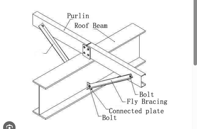
Installed in the roof plane, connecting the compression flanges of roof rafters—especially near mid-span where bending moments are highest.
Structural Role:
Provides lateral restraint to the rafter's top flange (which is typically in compression under gravity loads). This helps prevent lateral buckling under roof loads such as snow or dead weight.
Common Elements:
Angle or rod bracing
Sag rods
Cold-formed channels or angles
Cross bracing (X-type)
6.3.1.2. Eave Flange Bracing
Location:
Found near the eaves of the building, where the rafter connects to the column.
Structural Role:
Provides restraint to both the rafter and column flanges, especially in areas of complex stress distribution due to connections and load transitions.
Common Elements:
Short diagonal bracing members, sometimes connecting to eave struts or purlins.
6.3.1.3. Column Flange Bracing (Wall Bracing)
Location:
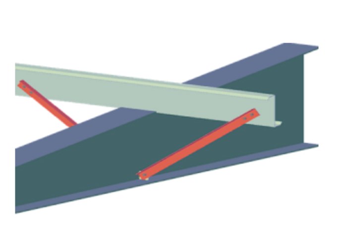
Installed in the wall plane, connecting to the flange of the columns, typically on the side under compression due to bending from wind or other lateral forces.
Structural Role:
Stabilizes the column flange in compression. Essential in resisting lateral-torsional buckling under lateral (wind/seismic) or vertical loads.
Common Elements:
Angles or tubular braces
Ties from flange to wall girts (or directly to horizontal bracing members)
Bracing connected through the wall sheeting plane
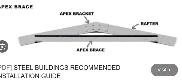
6.3.1.4. Ridge Bracing (Rafter Apex Bracing)
Location:
Located at the ridge (peak) of the building, especially in buildings with large spans or high-pitched roofs.
Structural Role:
Stabilizes the flanges of the rafters at the apex, which may experience compression due to negative bending (uplift conditions or wind suction).
Common Elements:
X-bracing
Rod or angle members
Diagonals that connect to the top purlins or across the ridge
6.4 CRANE SYSTEMS
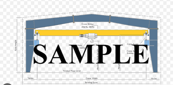
A crane system in a Pre-Engineered Building (PEB) refers to an integrated lifting mechanism—typically mounted on rails or beams within the building structure—that is used to lift, move, and position heavy loads efficiently within the building space. These systems are not standalone; they are fully coordinated with the building's structural design and are often a critical component in industrial, manufacturing, and logistics environments.
Crane systems may include overhead cranes, gantry cranes, jib cranes, or monorail systems. The most common type used in PEBs is the overhead traveling crane, which runs on rails attached to crane girders supported by the building's columns or separate supporting frames.
Crane systems greatly enhance the functionality and efficiency of a PEB, particularly in facilities where heavy materials, machinery, or products are moved frequently. Here are the key reasons they are so valuable:
Material Handling Efficiency
Crane systems enable fast and precise movement of heavy items, reducing manual labor and improving overall workflow. This is critical in production plants, warehouses, and fabrication shops.
Increased Safety
By automating lifting and movement tasks, crane systems reduce the risk of workplace injuries associated with manual handling or forklift operations.
Space Optimization
Unlike forklifts or conveyors, cranes use vertical and overhead space, freeing up valuable floor area for other operations or equipment.
Structural Integration
When a crane system is planned during the PEB design phase, it can be fully integrated into the building structure, resulting in cost savings, better load distribution, and seamless operation.
Support for Specialized Operations
Crane systems are often necessary for precision assembly, mold handling, machine maintenance, and shipping logistics, making them essential in many sectors.
Integrating a crane system into a PEB requires careful structural and functional coordination. Engineers must consider:
• Crane capacity (lifting load in tons)
• Span of crane and travel length
• Hoist speed and lift height
• Crane loading impacts on the building frame
• Crane runway beam design and deflection control
• Vibration, dynamic forces, and shock loads
• Maintenance access and safety clearances
The supporting frames, columns, bracing, and foundations must be designed to safely handle the vertical and horizontal forces generated during crane operations.
6.5 MEZZANINES
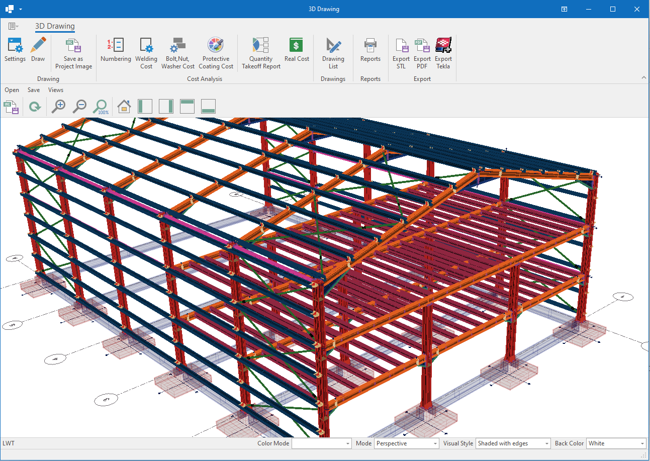
A mezzanine is an intermediate floor built between the main floors of a building, typically constructed within the clear height of a structure. In the context of Pre-Engineered Buildings (PEBs), a mezzanine is a steel-framed platform used to create additional usable space without expanding the building footprint.
Mezzanines do not typically extend across the entire building area; instead, they are partial floors placed where needed—usually for offices, storage, control rooms, or observation decks. They offer a practical and efficient way to make the most of the vertical space in a PEB.
Mezzanines play an important role in increasing the functionality and flexibility of Pre-Engineered Buildings. Here are the key reasons why they are commonly included:
Maximizing Space Without Expansion
Mezzanines allow for the creation of additional floor area without increasing the building’s footprint. This is especially valuable when land is limited or costly.
Cost-Effective Area Expansion
Building a mezzanine is significantly cheaper than constructing an entirely new building or extension, making it a budget-friendly option for growing businesses.
Functional Separation
Mezzanines are often used to separate functions within the same building—for example, a warehouse on the ground floor and office or control space on the mezzanine level.
Improved Workflow and Storage
In industrial or logistic applications, mezzanines can help streamline operations by providing elevated storage, staging areas, or dedicated workspaces, improving organization and efficiency.
Adaptability and Future Modifications
A mezzanine structure can often be modified, expanded, or relocated within the building, offering flexibility for changing needs over time.
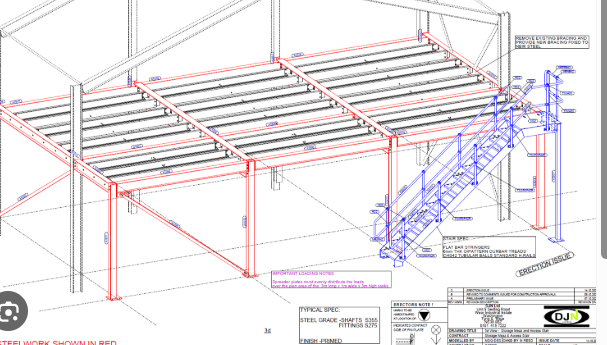
In a PEB, mezzanines are designed as secondary structures supported by the main frame or independent columns. The design includes:
• Primary beams: Main support members spanning across mezzanine columns
• Secondary joists: Lighter members spaced across beams to support the floor deck
• Decking: Typically made of metal decking and a concrete slab for heavy-duty use
• Access: Stairs, ladders, or lifts may be included depending on usage
The design must account for:
• Load-bearing requirements (people, storage, equipment)
• Deflection limits to ensure comfort and safety
• Clear height beneath and above the mezzanine
• Integration with services such as lighting, HVAC, and sprinklers
6.6 ENDWALL
In a Pre-Engineered Building (PEB), the endwall refers to the structural system located at the very ends of the building, perpendicular to the main frames.
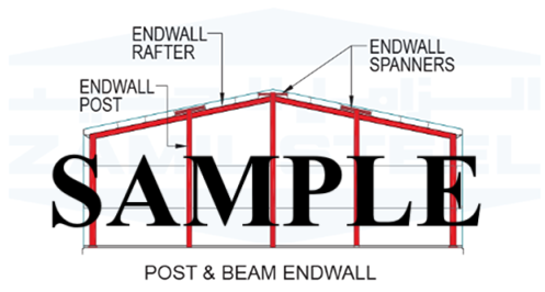
While the main frames handle the majority of the building’s vertical and lateral loads, endwalls play several key roles in the overall stability and functionality of a PEB:
Structural Support (When Required)
In some cases, especially for smaller or lighter buildings, endwalls may also carry part of the roof load and wind loads. These are known as rigid endwall frames, and they function similarly to interior main frames.
Building Enclosure
Endwalls help fully enclose the structure, providing a finished appearance and protection from environmental elements such as wind, rain, and dust. They also provide surfaces for cladding, doors, windows, and ventilation components.
Support for Openings
Endwalls are often used to support access points like rolling shutters, personnel doors, glass panels, or ventilation louvers. Their design must account for these openings while maintaining structural integrity.
Cost Efficiency
When structural loads are minimal at the ends of the building, designers may opt for a non-expensive endwall system with lighter members known as "post-and-beam" systems, rather than rigid frames. This helps reduce material costs and fabrication time.
Future Expansion
In many PEB designs, endwalls are left flexible to allow for future building extensions. If a client wants to increase the building length later, removing or modifying the endwall is much easier than altering a main frame.
When designing endwalls, engineers take into account:
• Local wind pressures and environmental loads
• Presence of doors, windows, and vents
• Connection to roof and wall panels
• Type of cladding material
• Aesthetic or architectural requirements
• Potential for future expansion
Proper design ensures that the endwall system works in harmony with the rest of the structure, providing both stability and flexibility.
6.7 SAG RODS
Sag rods are slender, tension-resisting members—typically made of steel rods—that are installed horizontally or diagonally between adjacent purlins (roof) or girts (wall). Their primary purpose is to limit the lateral movement and sagging (deflection) of these secondary framing members under load.
In PEBs, purlins and girts are usually light-gauge, cold-formed steel sections with open profiles, such as Z- or C-shapes. When subjected to loads like the weight of roof panels, wind pressure, or their own self-weight, these members can twist or bend laterally. Sag rods help tie them together and stabilize them, making them behave more like a unified system.
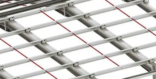
Sag rods are tension-only members. They do not resist compression and are typically made from mild steel rods or cables with threaded ends for bolted connections.
When loads cause a purlin to sag downward or twist, the sag rod acts in tension to pull it back into alignment, effectively bracing the member’s weak axis and reducing unsupported length.
In long spans, a system of sag rods may be arranged in a zig-zag or diagonal pattern, creating a bracing grid across the roof plane.
