MkaPEB Engineering Output Package
Standards define the minimum rules to be followed when designing a steel structure. The people who control the project check that the standards are met.
It is important that the reports are understandable, clear, detailed and traceable.

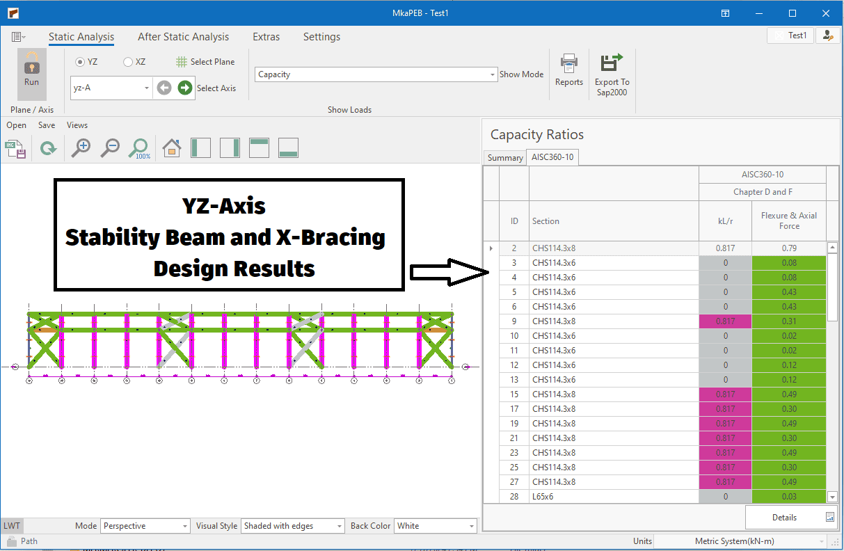
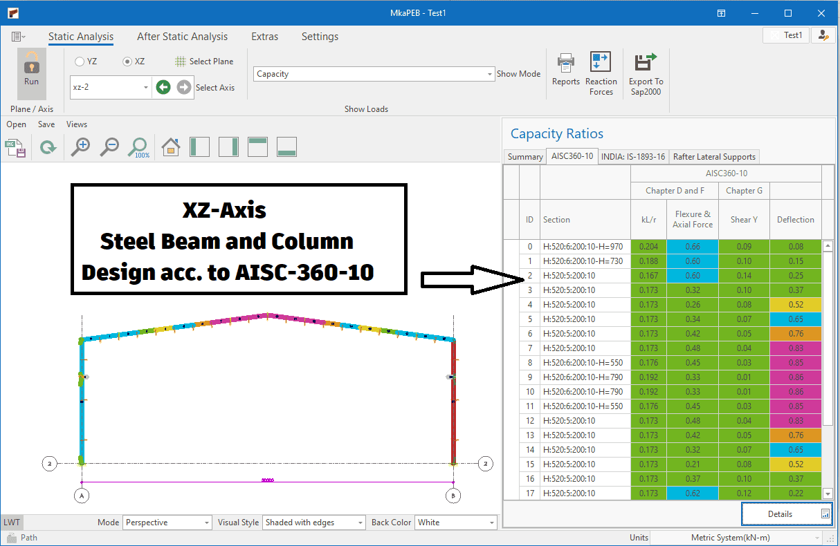
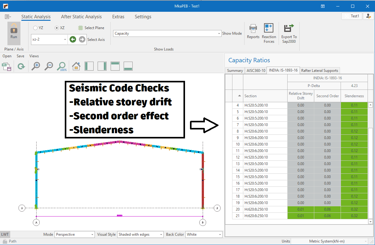
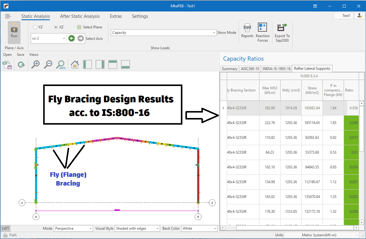
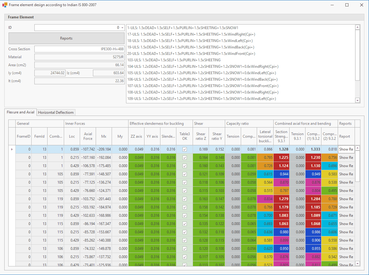
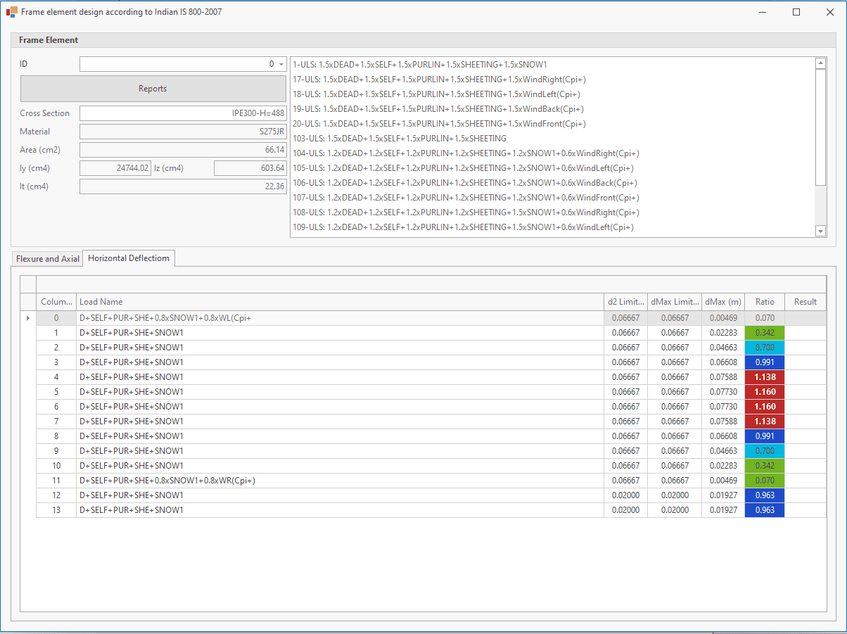
Steel frame element design results
Seeing the design results quickly and simply speeds up the engineer's decision-making process. For this reason, MkaPEB has user-friendly interfaces.
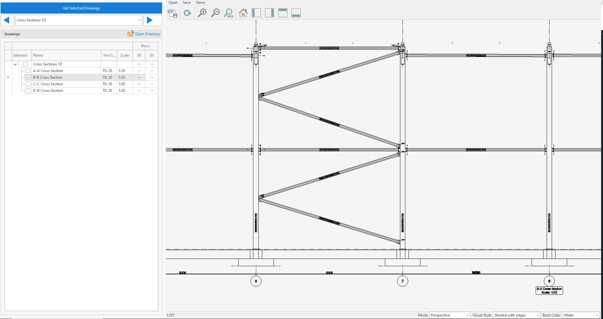
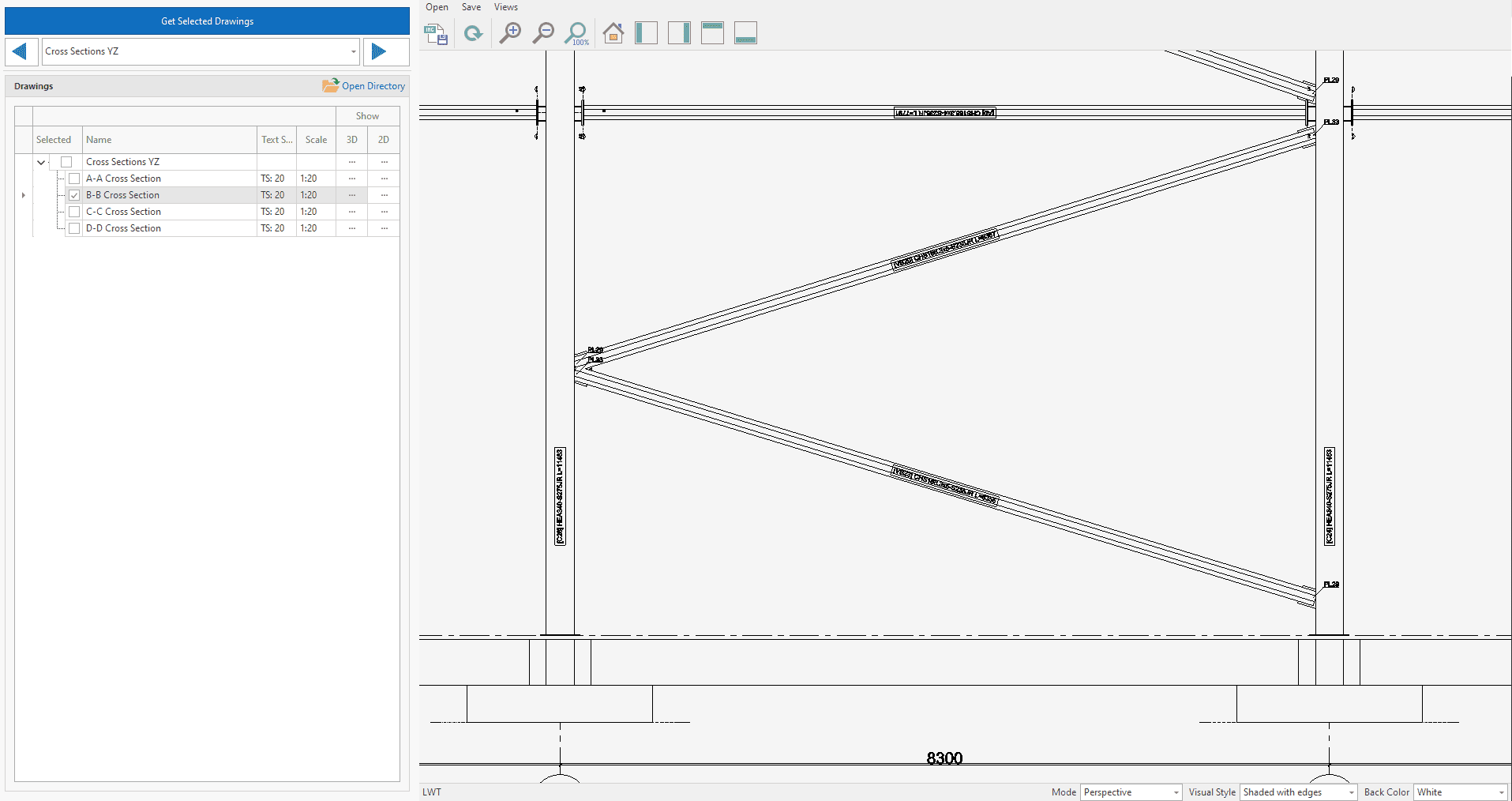
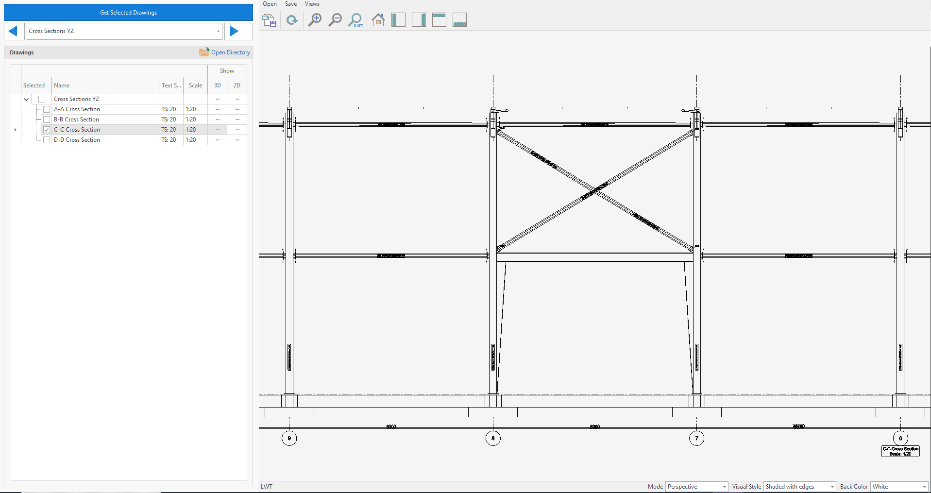
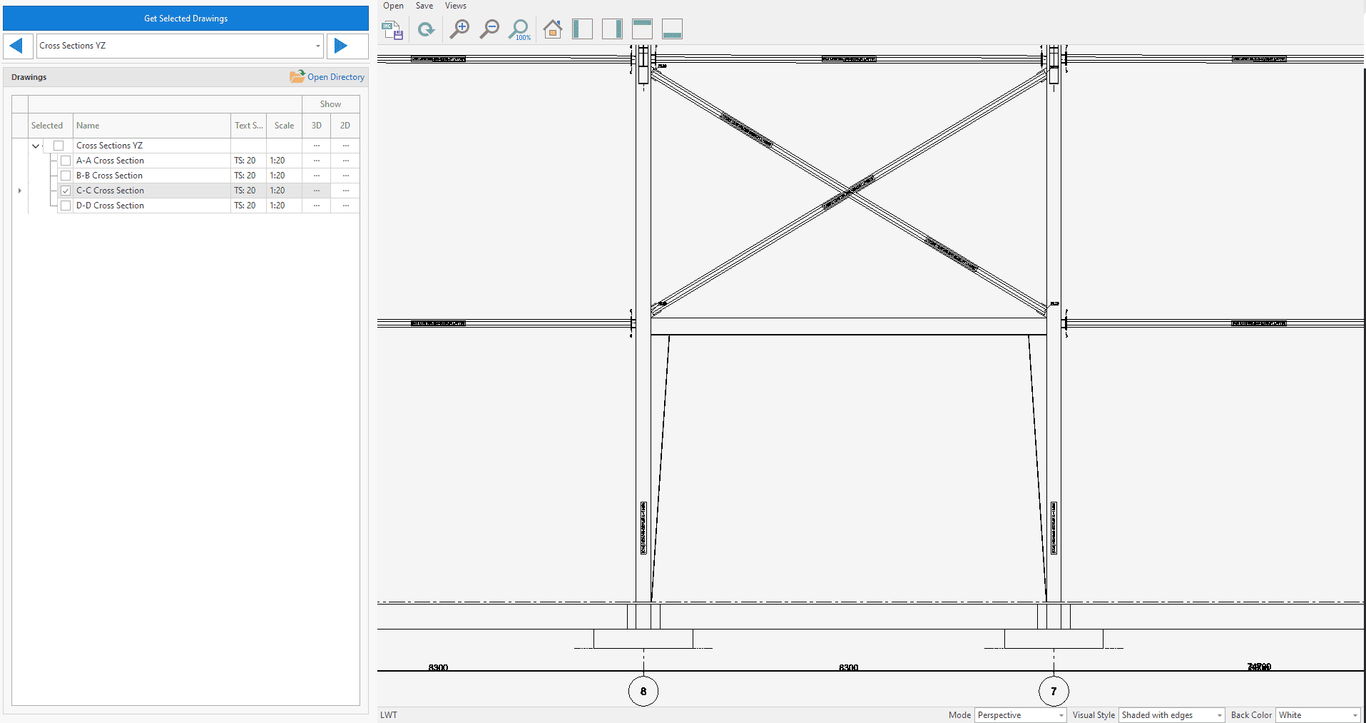
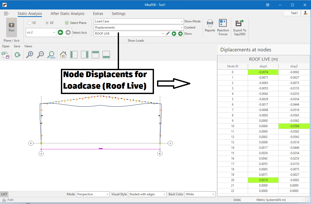
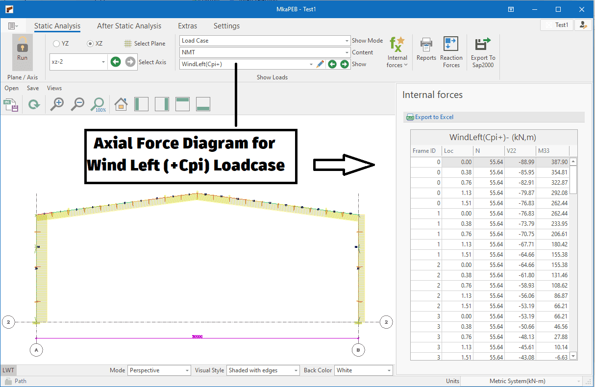
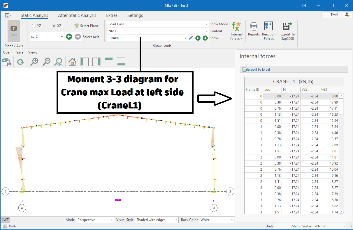
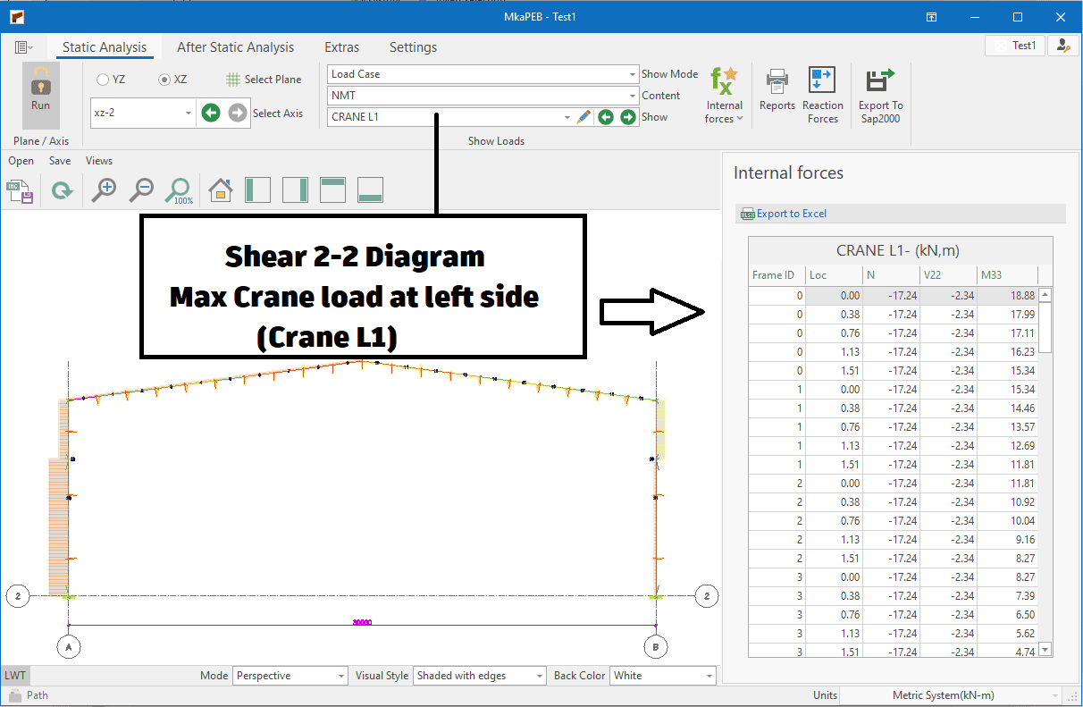
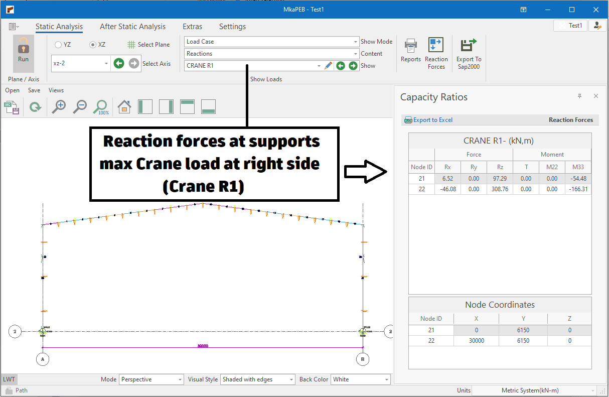
Structural analysis results
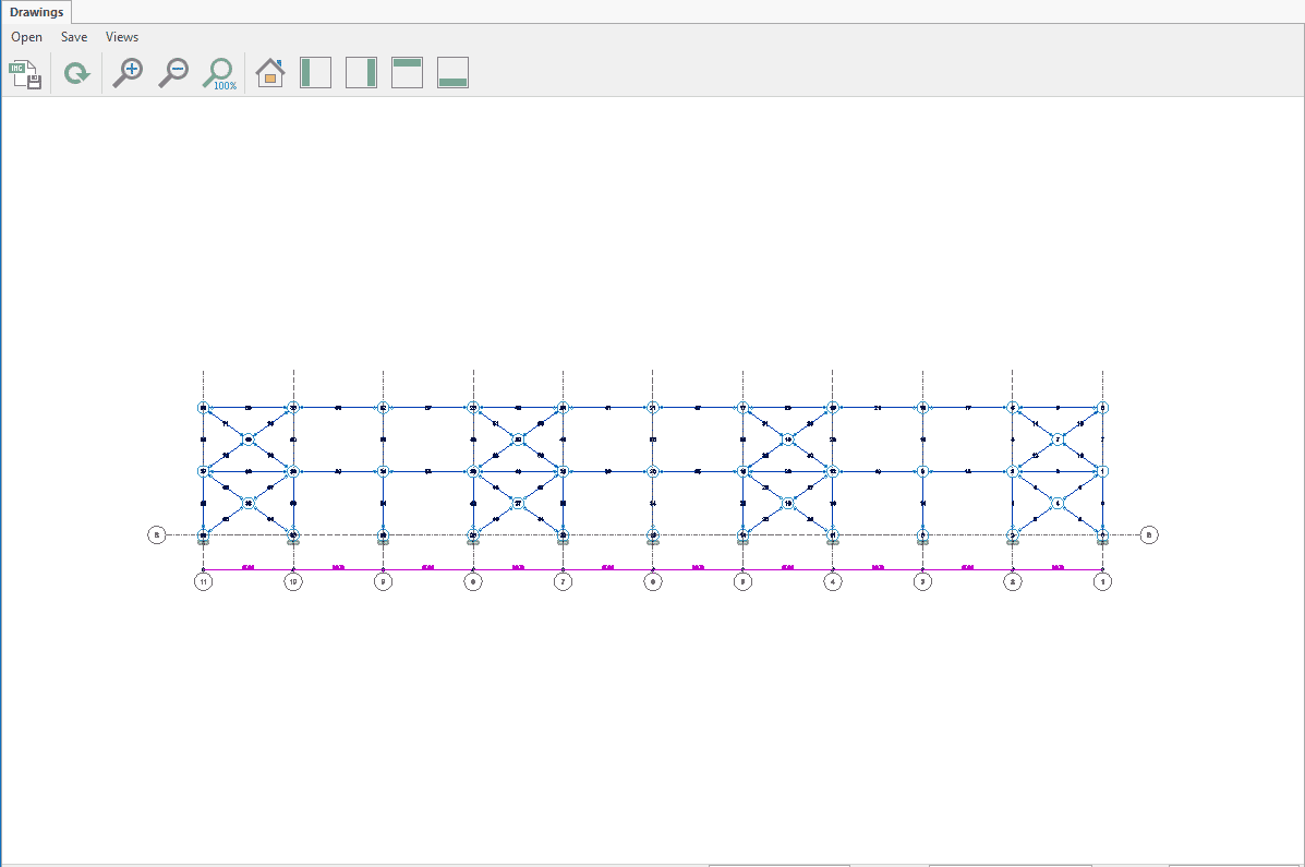
Engineers often want to see the behaviour of the structure under loads. For this purpose, they examine displacement, axial and shear force, moment and reaction force diagrams. In this way, they can check whether the support and starting/ending releases are defined correctly.
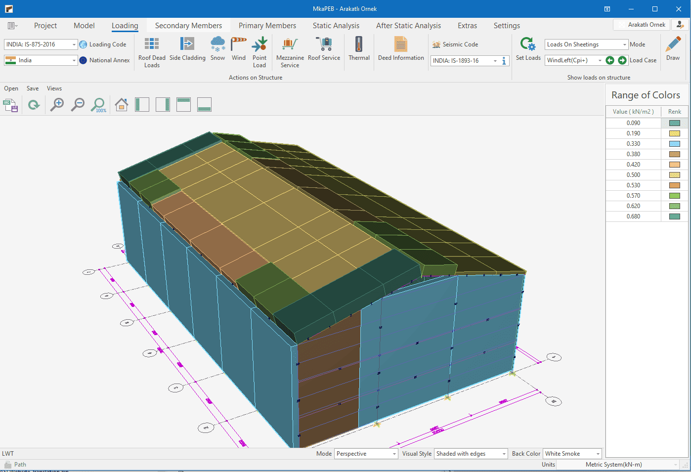
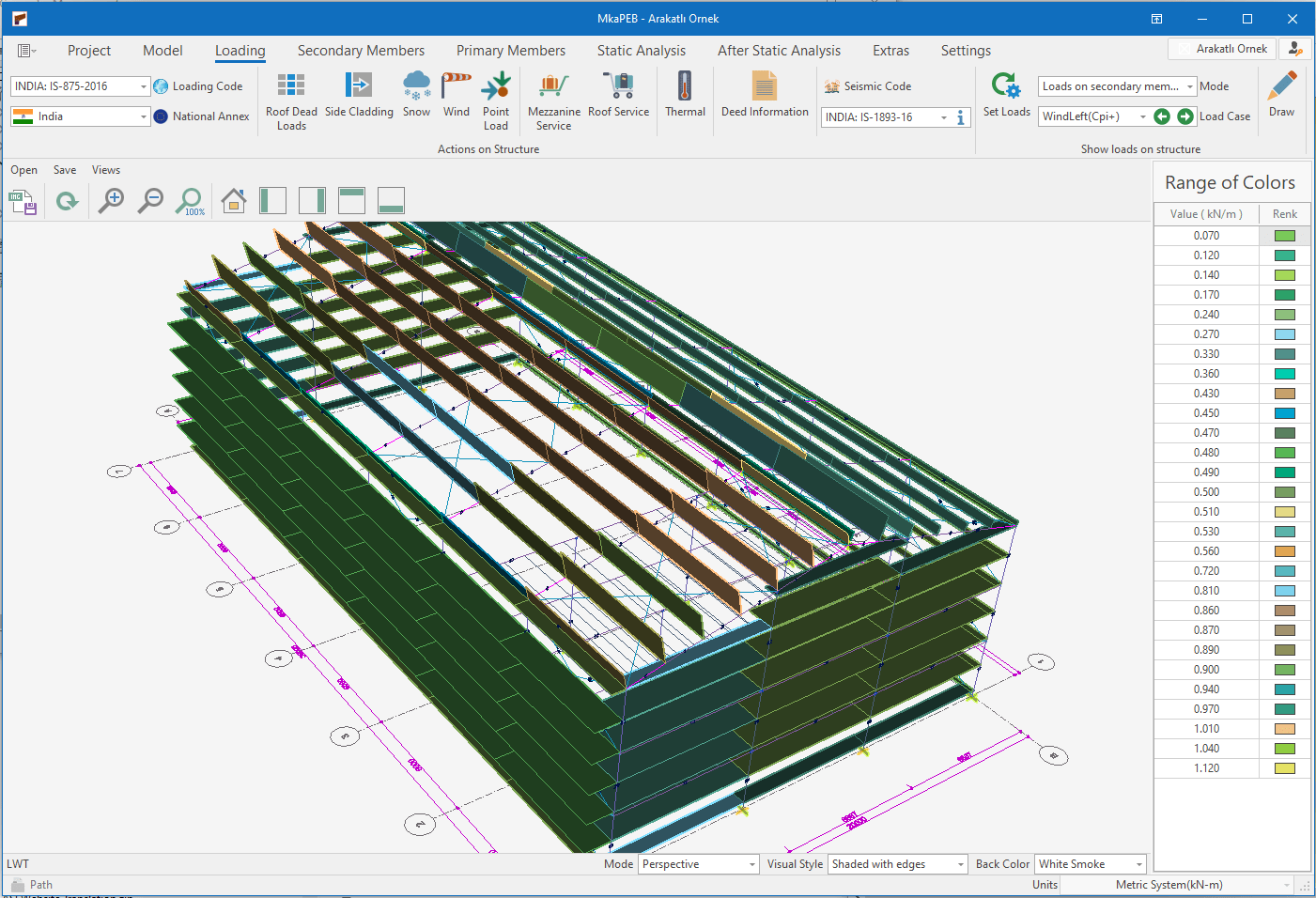
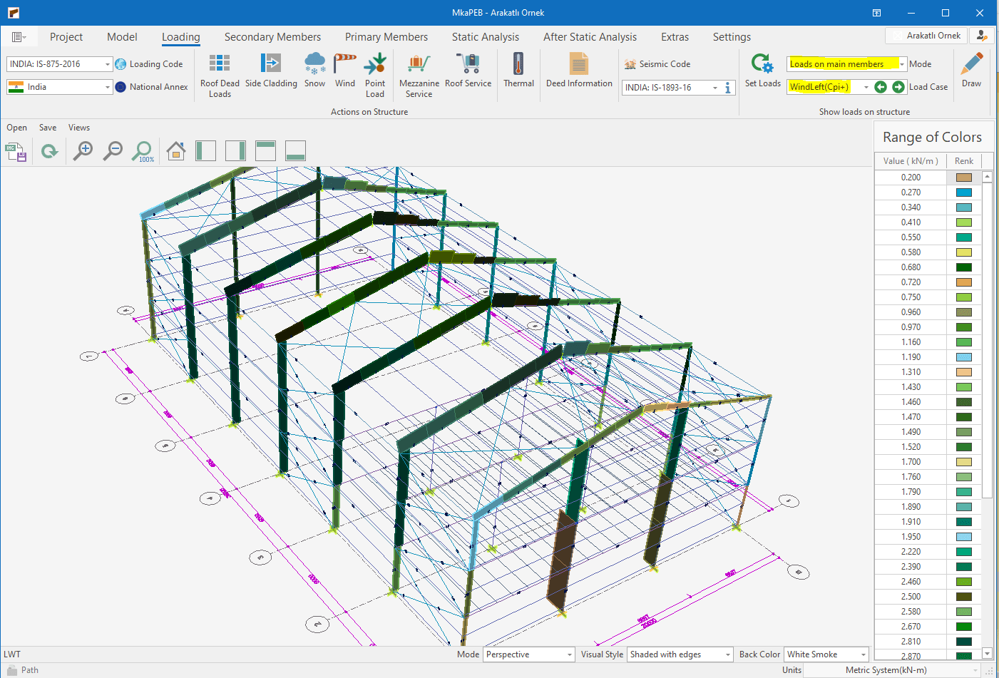
Loads acting on structure
For structural design, a building model is created, disaster loads are applied on this model and it is checked whether the structure can withstand this disaster. The loads acting on the structure are very important here, experienced engineers want to see how these loads are assigned.
The loads acting on the structure are first transferred to the shell elements, then to the secondary structural elements and then to the primary structural elements. MkaPEB follows this sequence in nature.
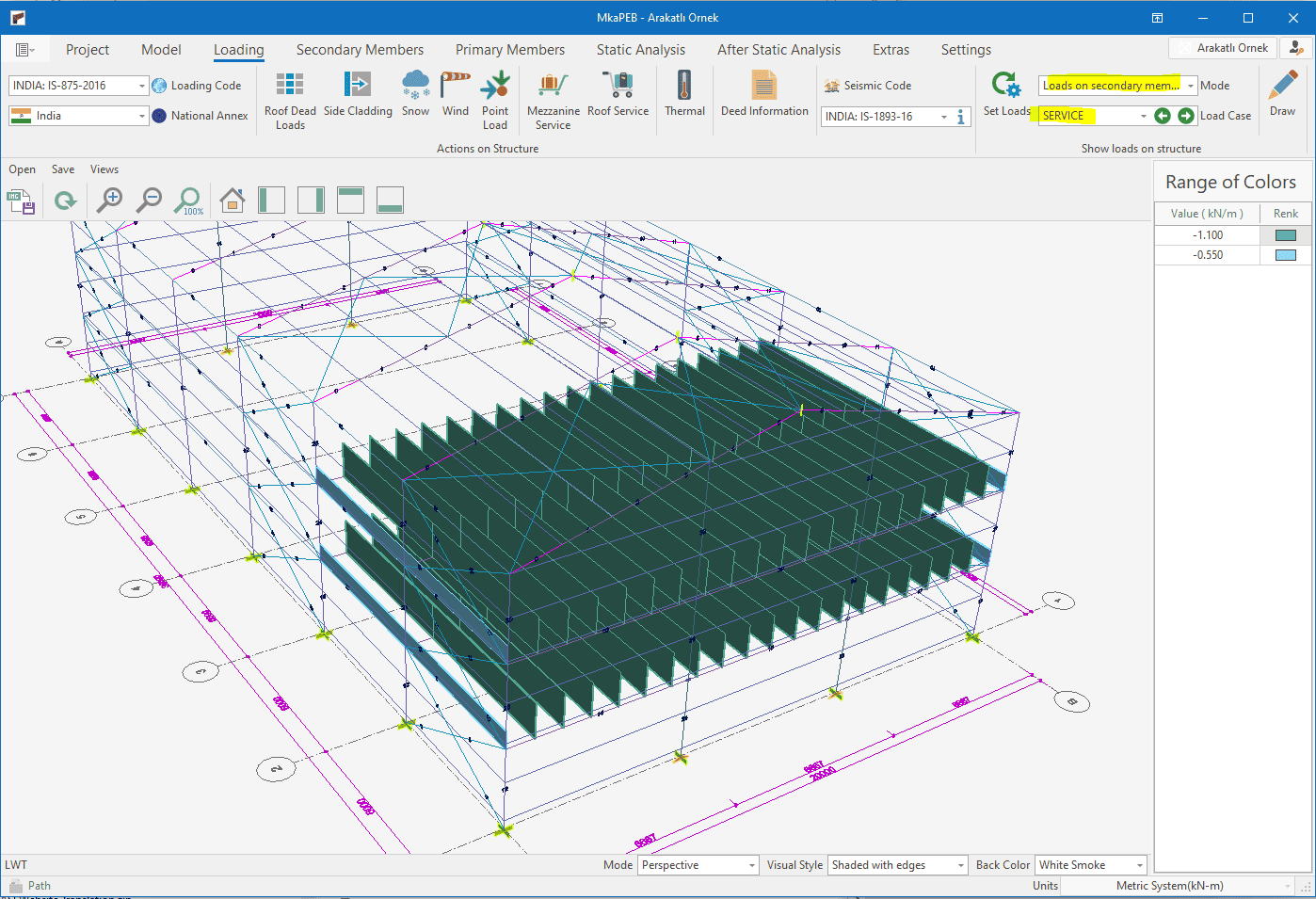
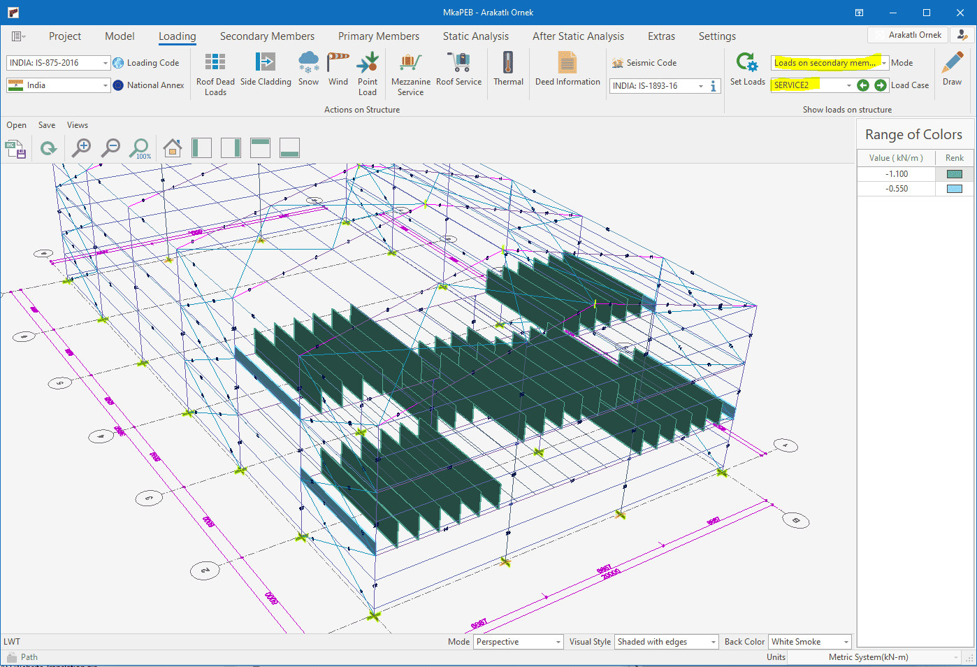
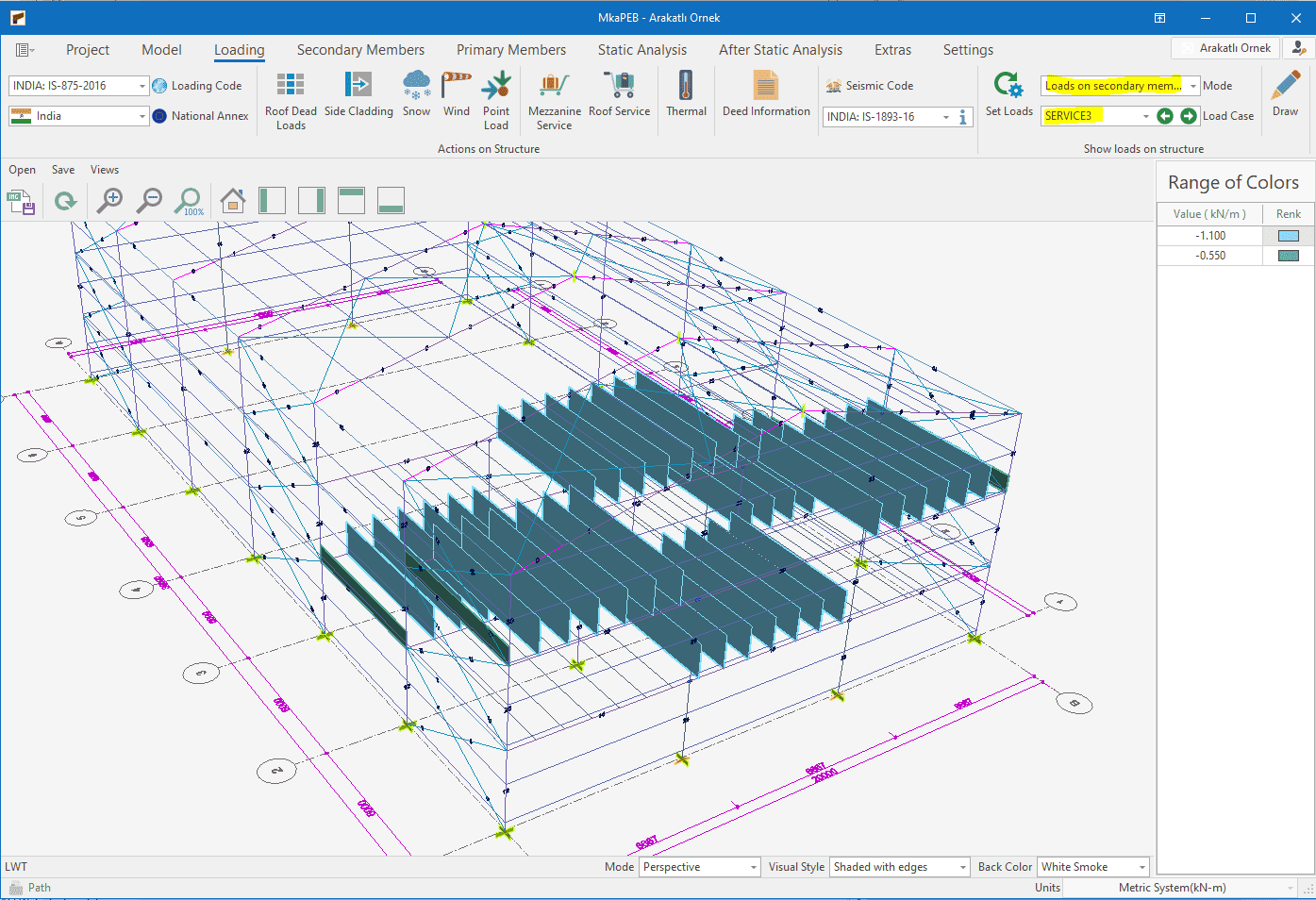
Special Service Loads for Mezzanines
The location of service loads on mezzanine floors is always an unknown. Engineers can only find the position that is likely to put the structure in the most difficult situation by experimenting. MkaPEB has 3 different automatic service loads to speed you up.
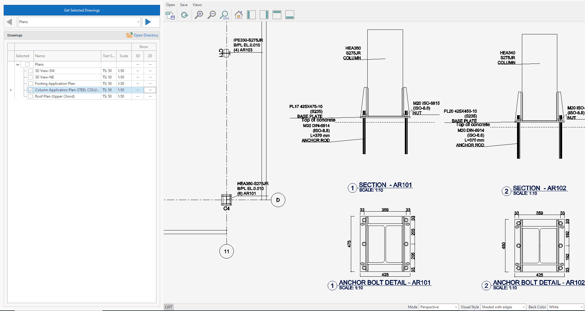
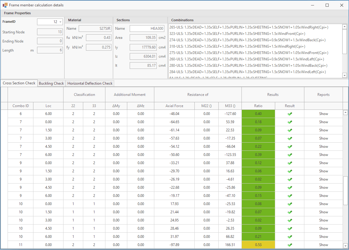
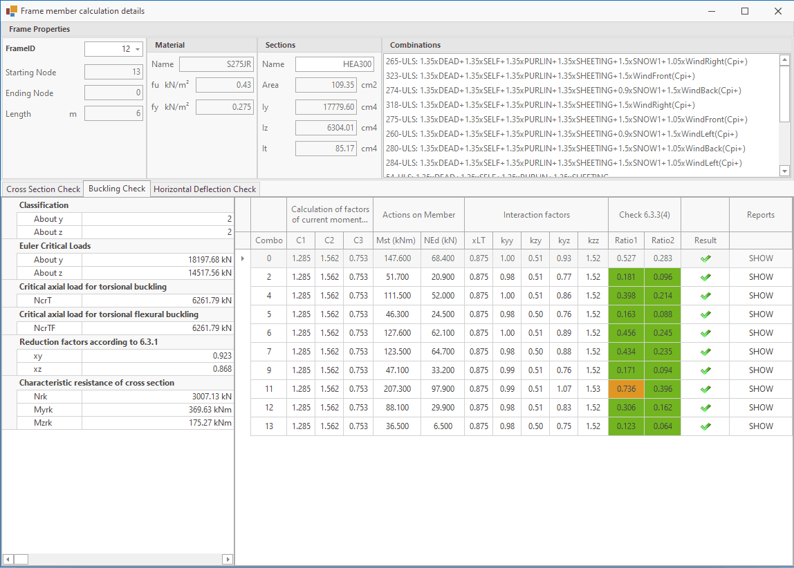
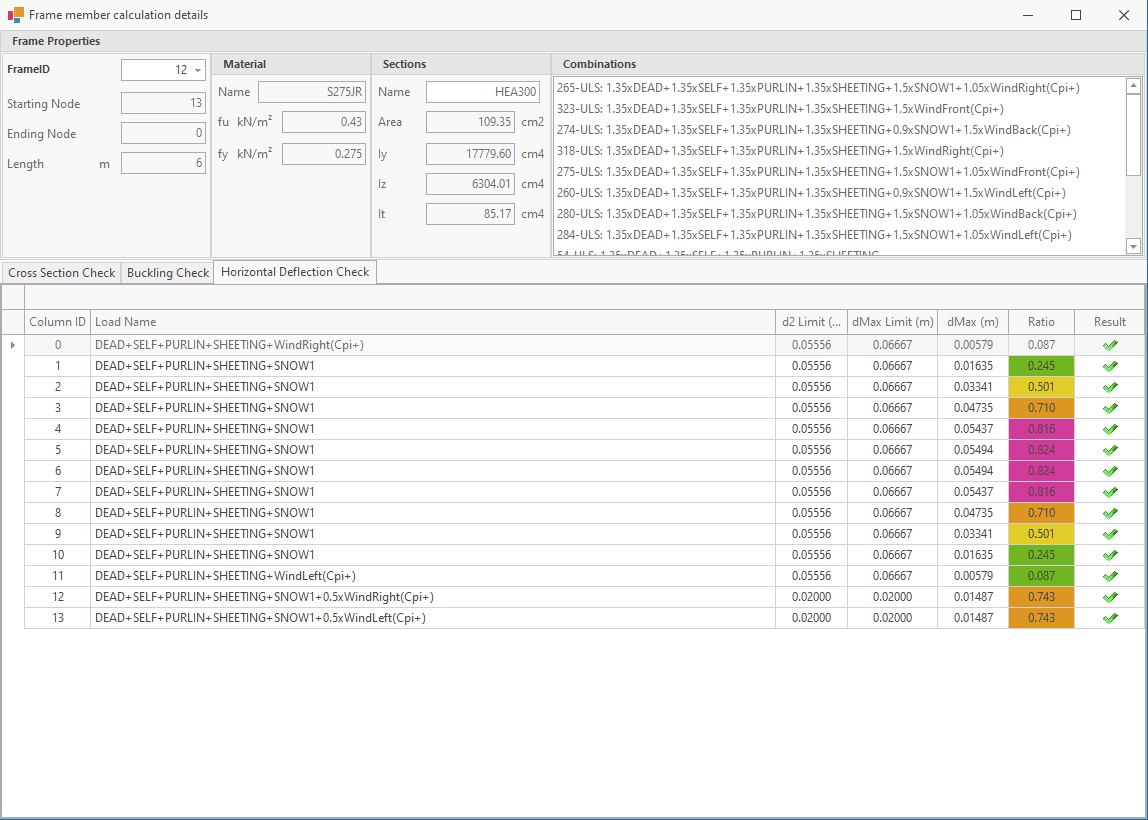
Detailed Member Design Reports
In the present era, a considerable number of software applications offer the functionality of displaying calculation results in tabular form. Verification examples are provided as evidence that the calculations are accurate. In light of the intricate nature of the design codes, it is not feasible to assert that the calculations are entirely accurate. Nevertheless, these studies are invaluable in demonstrating that the calculations have been subjected to meticulous scrutiny.
In contrast, MkaPEB employs a distinct approach. The calculations are presented in comprehensive detail by substituting values in references, formulae, and formulae. Each report serves as a verification sample.
EN-1991-1-1: 2005
Design of steel structures - Part 1-1: General rules and rules for buildings
AISC-360-16
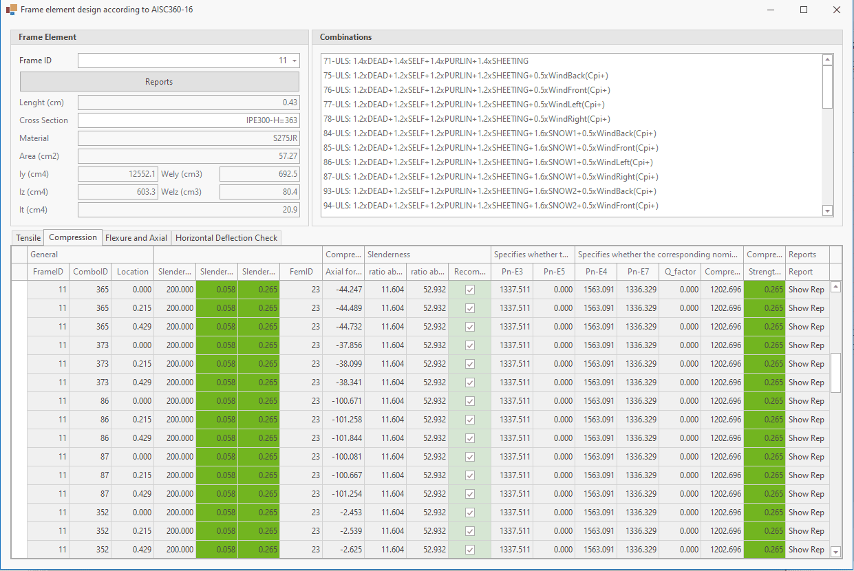
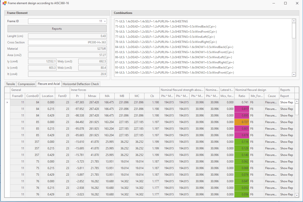
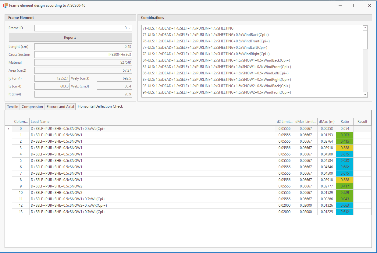
Specification for Structural Steel Buildings
IS-800:2007
General Construction In Steel - Code of Practice
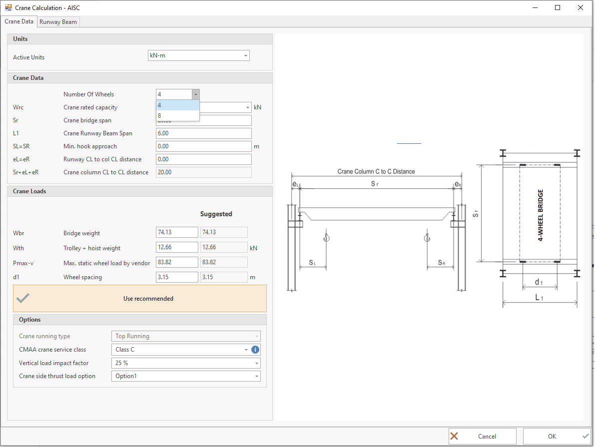
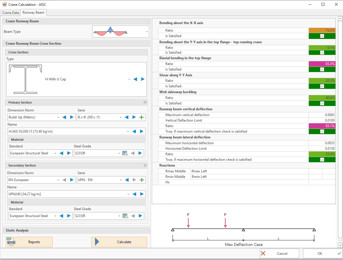
Overhead Crane Design Reports
There is often an overhead crane in hangar type steel structures. Wheel reactions of these cranes are very important for structural design. MkaPEB can calculate the reaction forces on the wheels according to AISC Design 7 or EN-1991-3. The values given by the crane manufacturers can also be used, but it is expected to be close to the values in the regulations.
The crane runway beam is part of the structural system. Just as a sandwich panel company cannot change the roof purlins, the crane runway beam cannot be determined by the crane manufacturer.
Detailed reports prepared by MkaPEB for crane walkway design are given below.
AISC Design Guide 7
Industrial Building Design
EN-1991-3
Specifies imposed loads (models and representative values) associated with cranes on runway beams and stationary machines
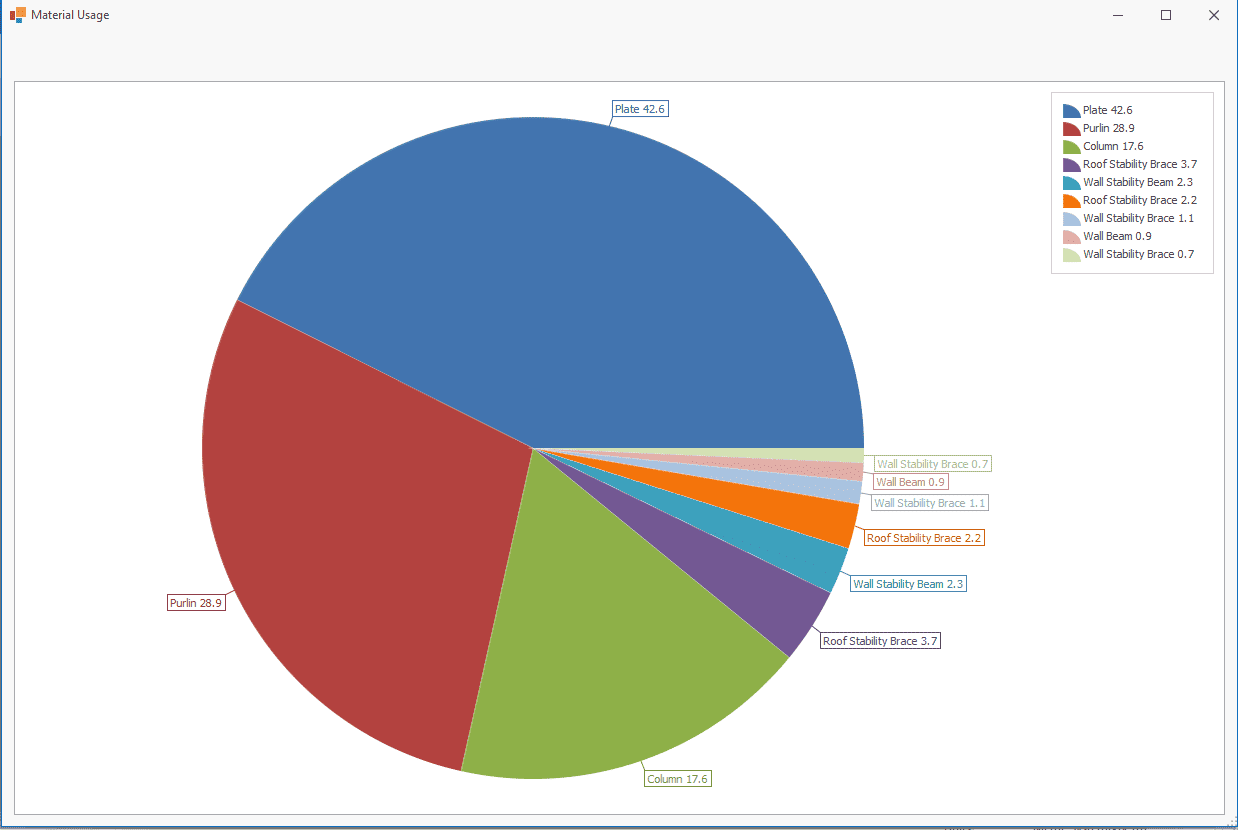
Importance of Cost Analysis
The first question a client asks us is the approximate cost of the building. The quick, accurate and most economical answer to this question determines whether or not the job will be taken on. To achieve the desired goal, a large number of alternatives must be compared and evaluated. MkaPEB helps you in this phase.
The faster we can model the structure, calculate the allowable loads, apply them to the structure and determine whether our choices are adequate under the influence of the loads, the more alternatives we can try.
Let's consider the construction cost as material + labour. Labour in steel fabrication can be considered as sandblasting, drilling and cutting of profiles and plates, assembling and welding, painting, quality control and assembly.
Portal frames can be manufactured using rolled or fabricated profiles. It may be possible to produce a structure using 40kg/m2 steel with very little welding using rolled profiles, or using 25kg/m2 steel as PEB using fabricated profiles, but with much more welding. Presenting these two alternatives to the client will show that you are thinking about the client as well as your mastery of the subject.
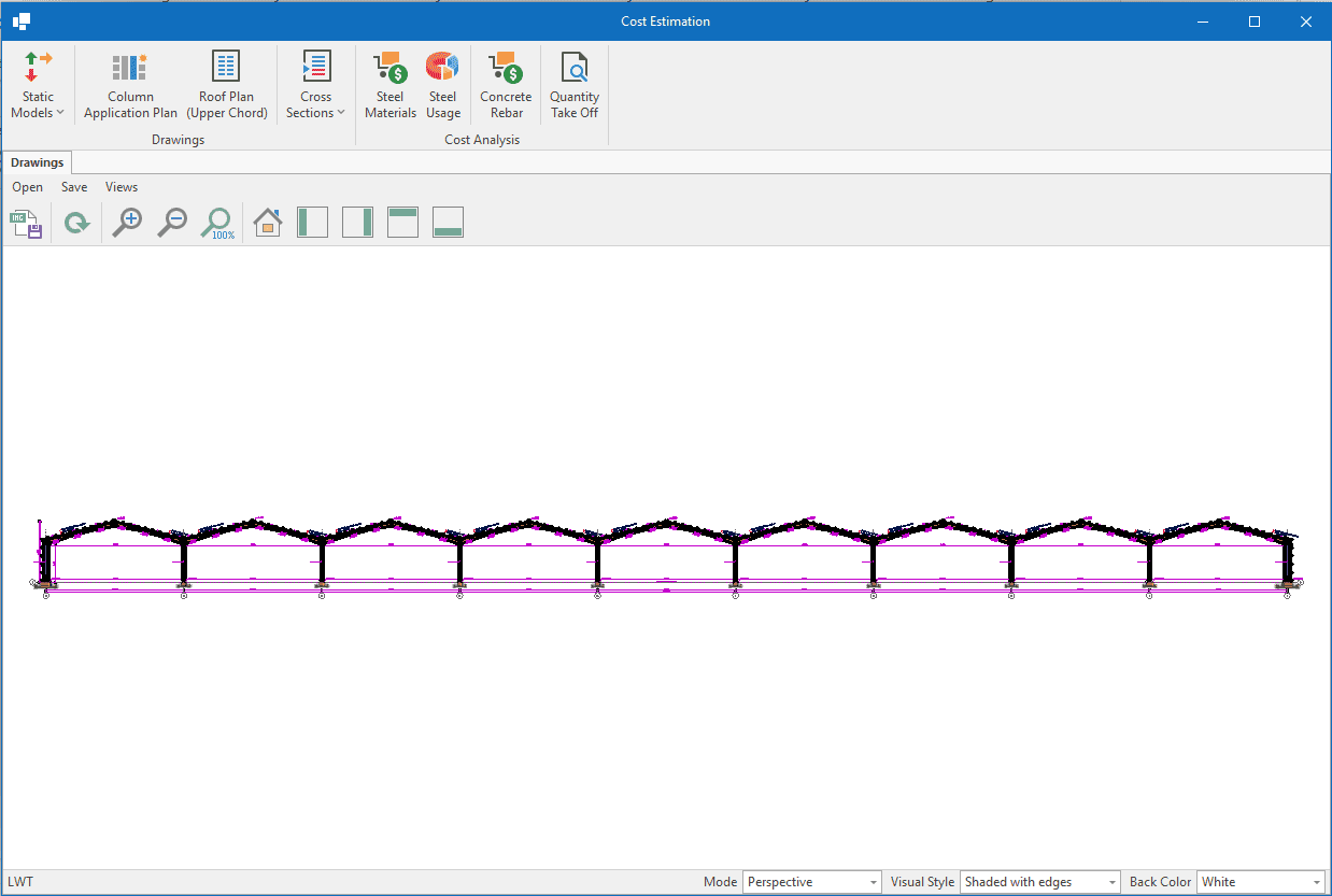
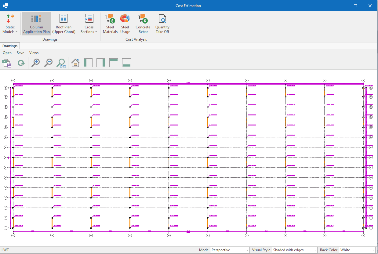
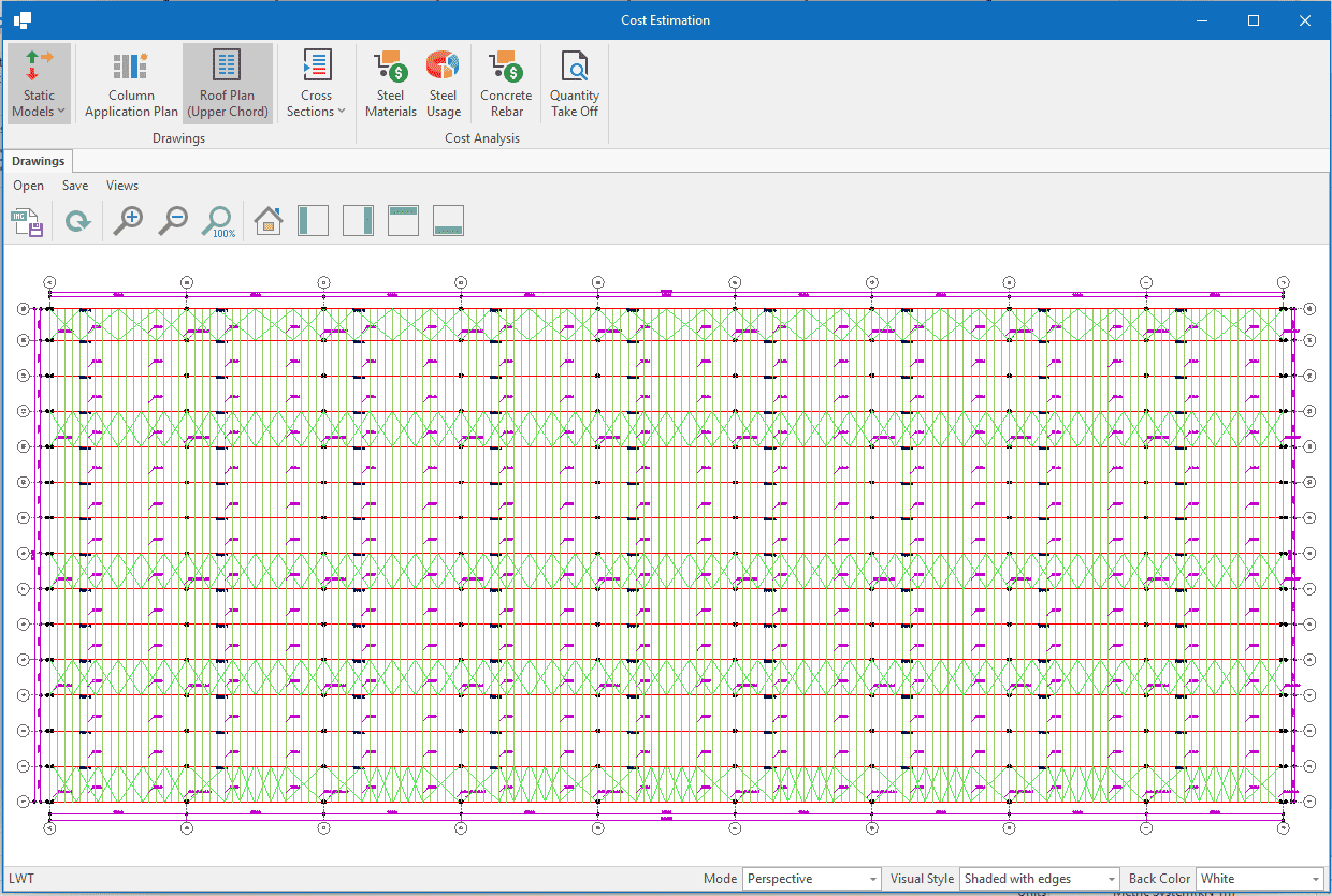
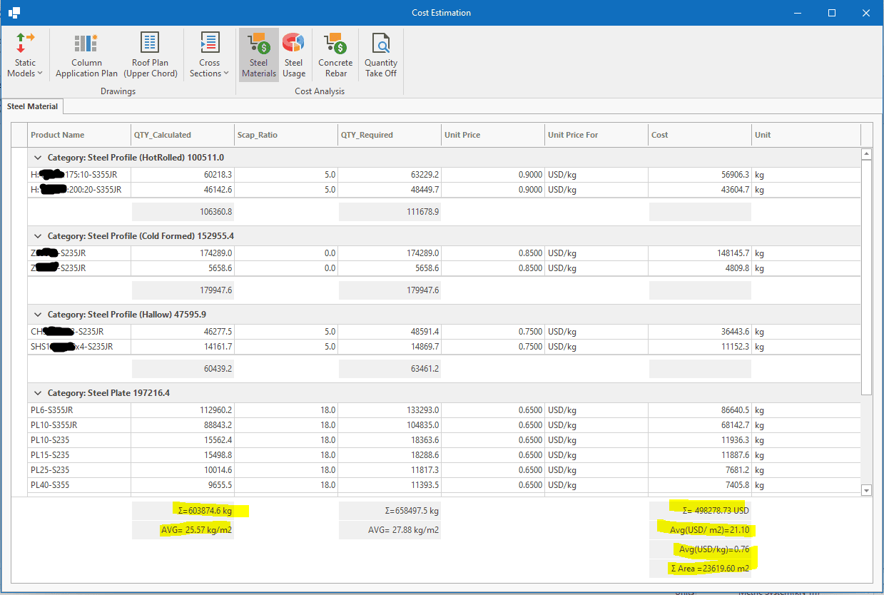
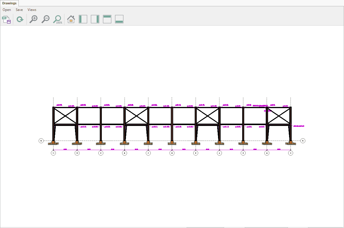
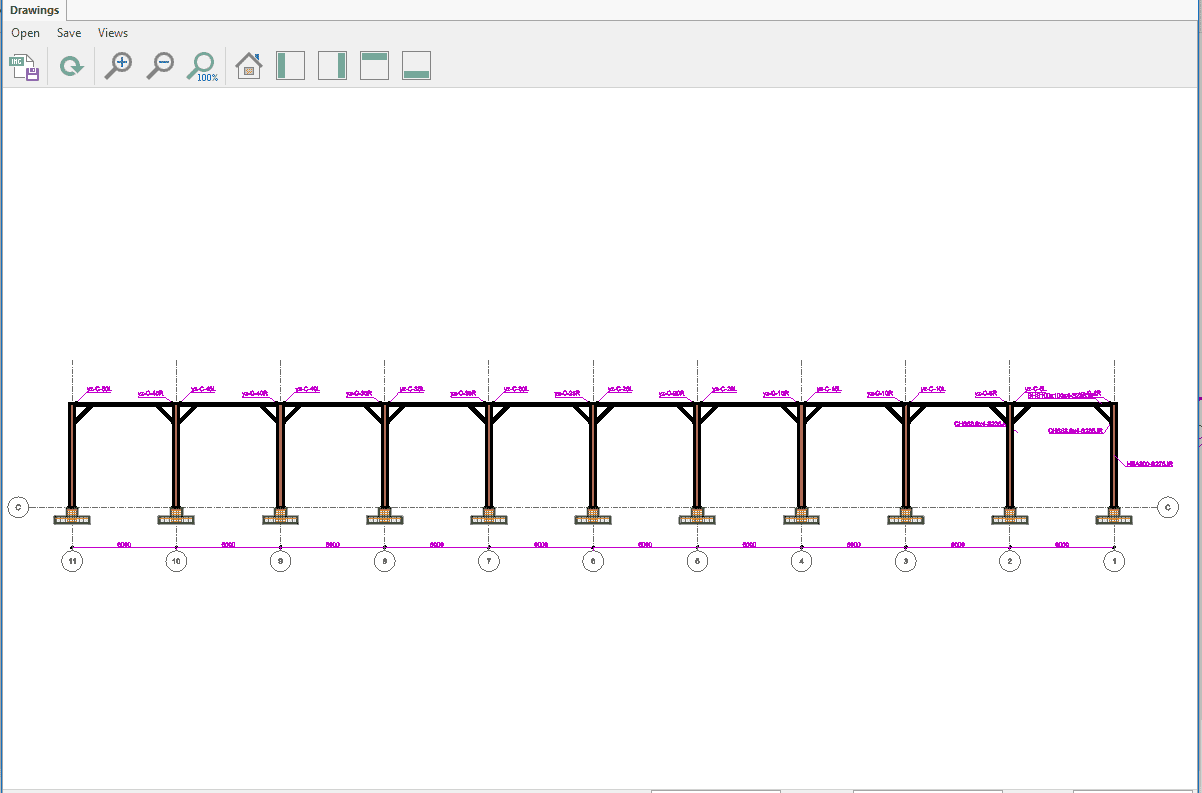
Cost analysis window
Information of the building for which the cost analysis was performed:
- 9 x 27m =243 m portal frames,
- Column height=8.5 m
- Loads on roof, 0.85 kN/m2 snow, 0.21 kN/m2 ice, 0.15 kN/m2 solar panel, 0.1 kN/m2 roof sheeting, 0.05 kN/m2 equipment, totaly=1.36 kN/m2
- Wind speed= 28 m/s
- Building width= 14 x7 m=98m
- Total Area= 23,800 m2
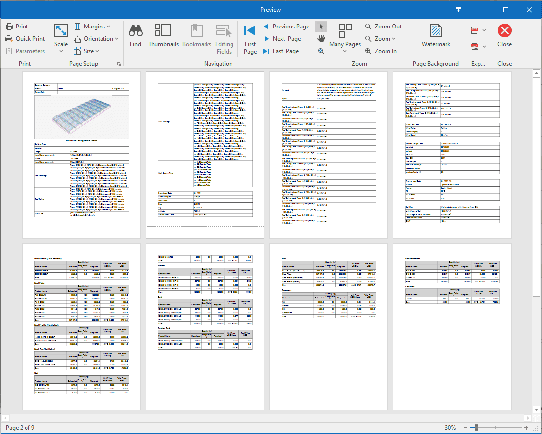
Calculation Report Content
At the beginning of the project's calculation report, the design principles of the project are given. The design principles should contain at least the following information.
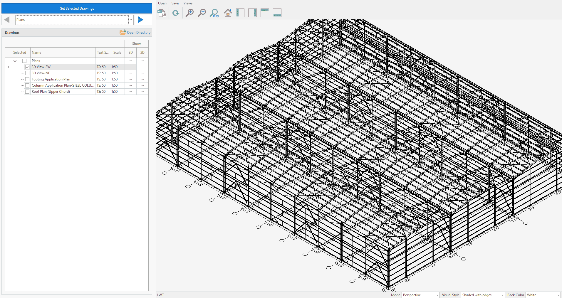
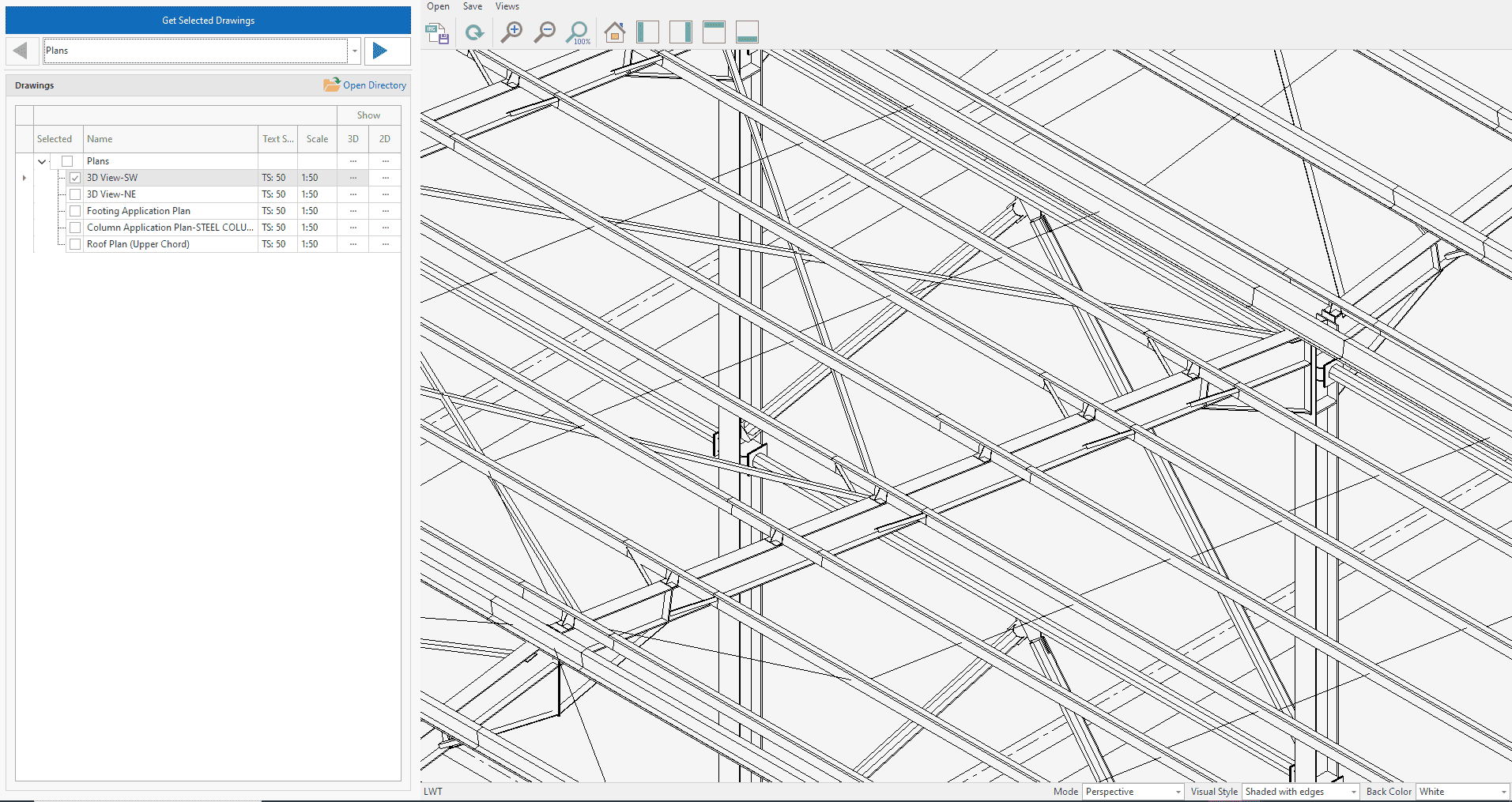
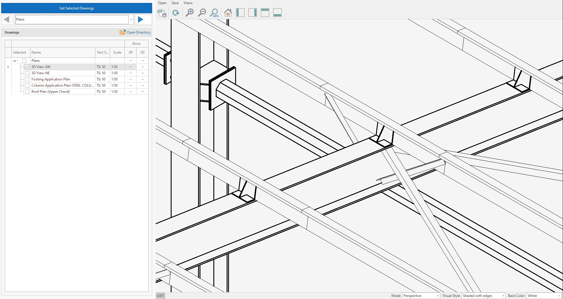
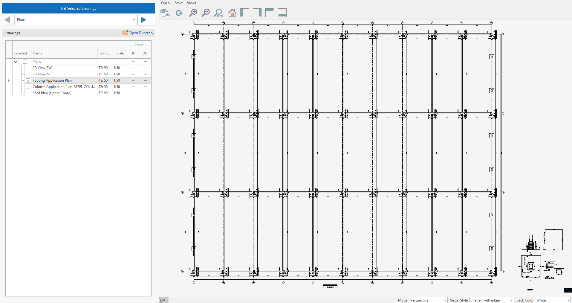
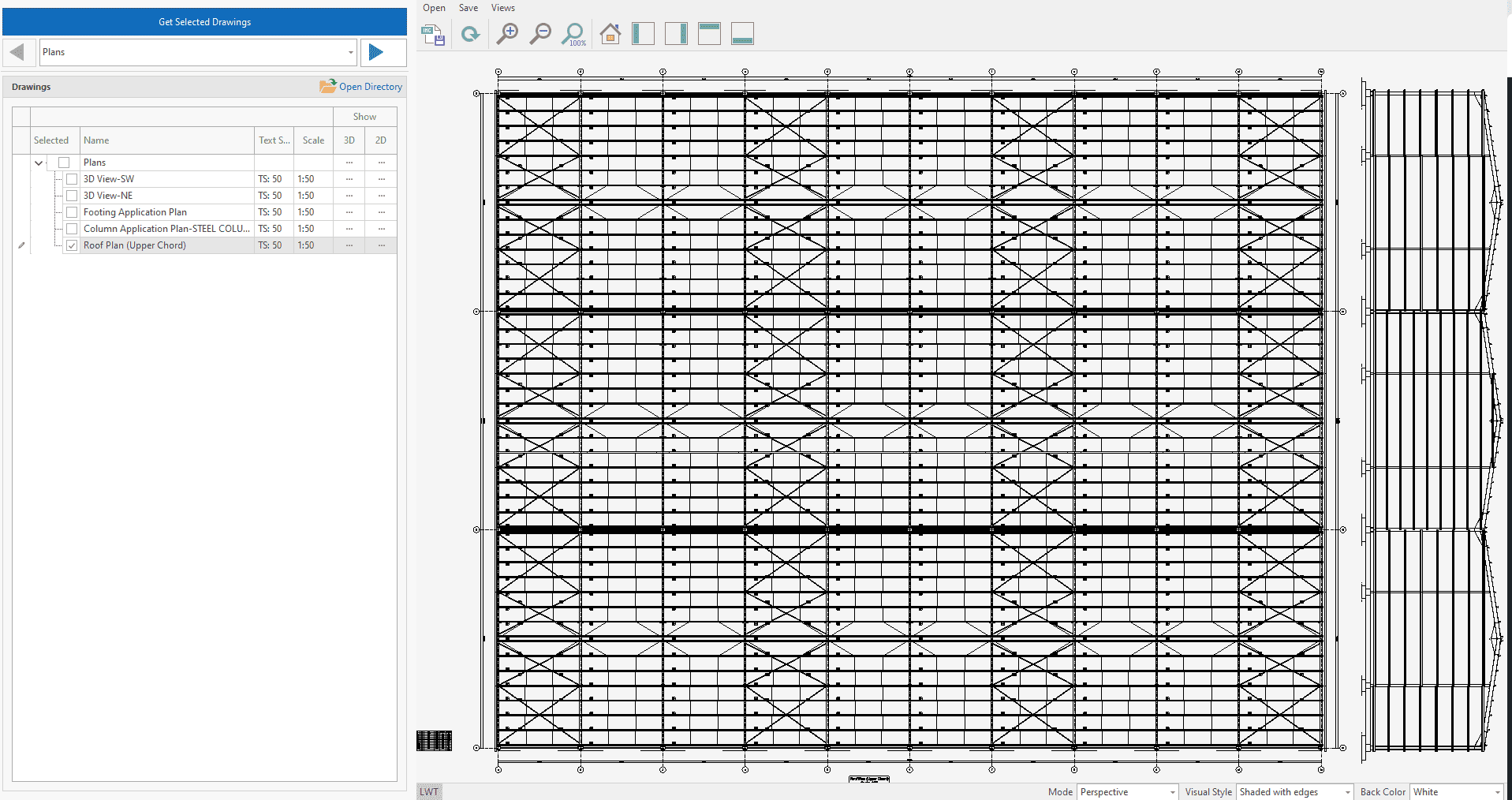
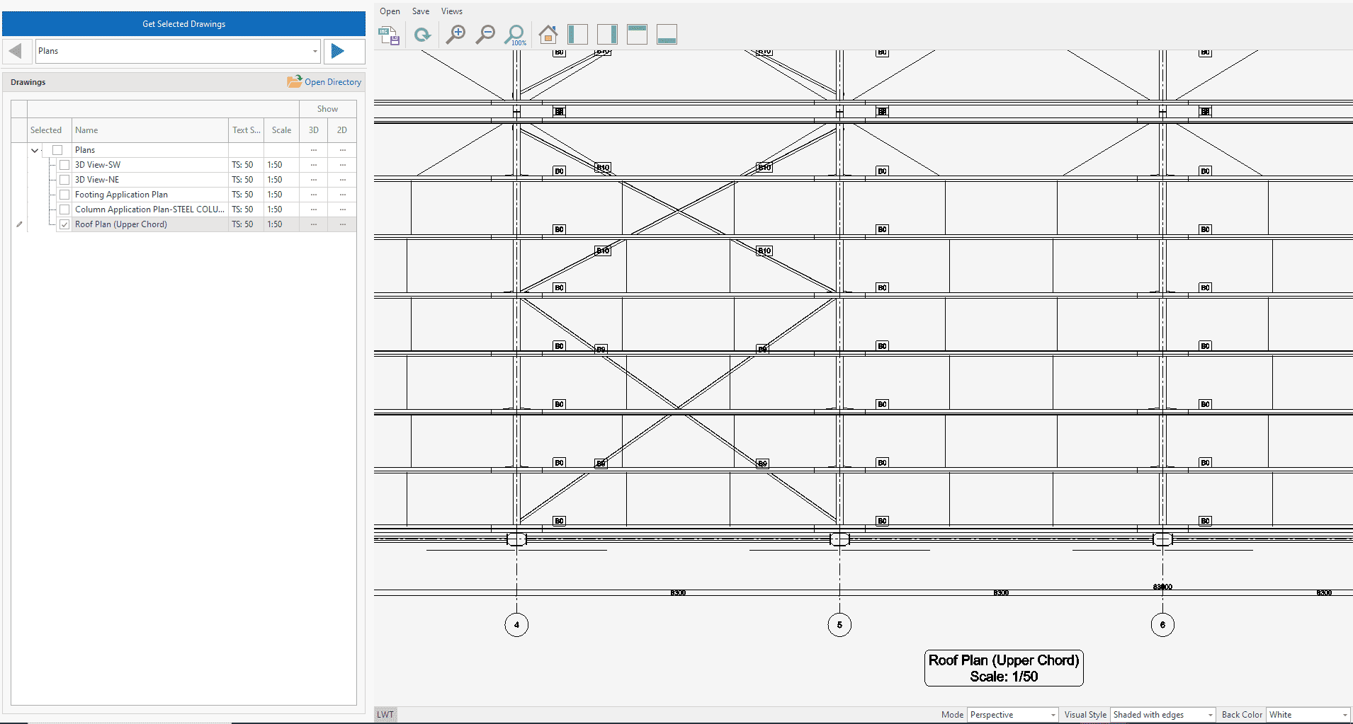
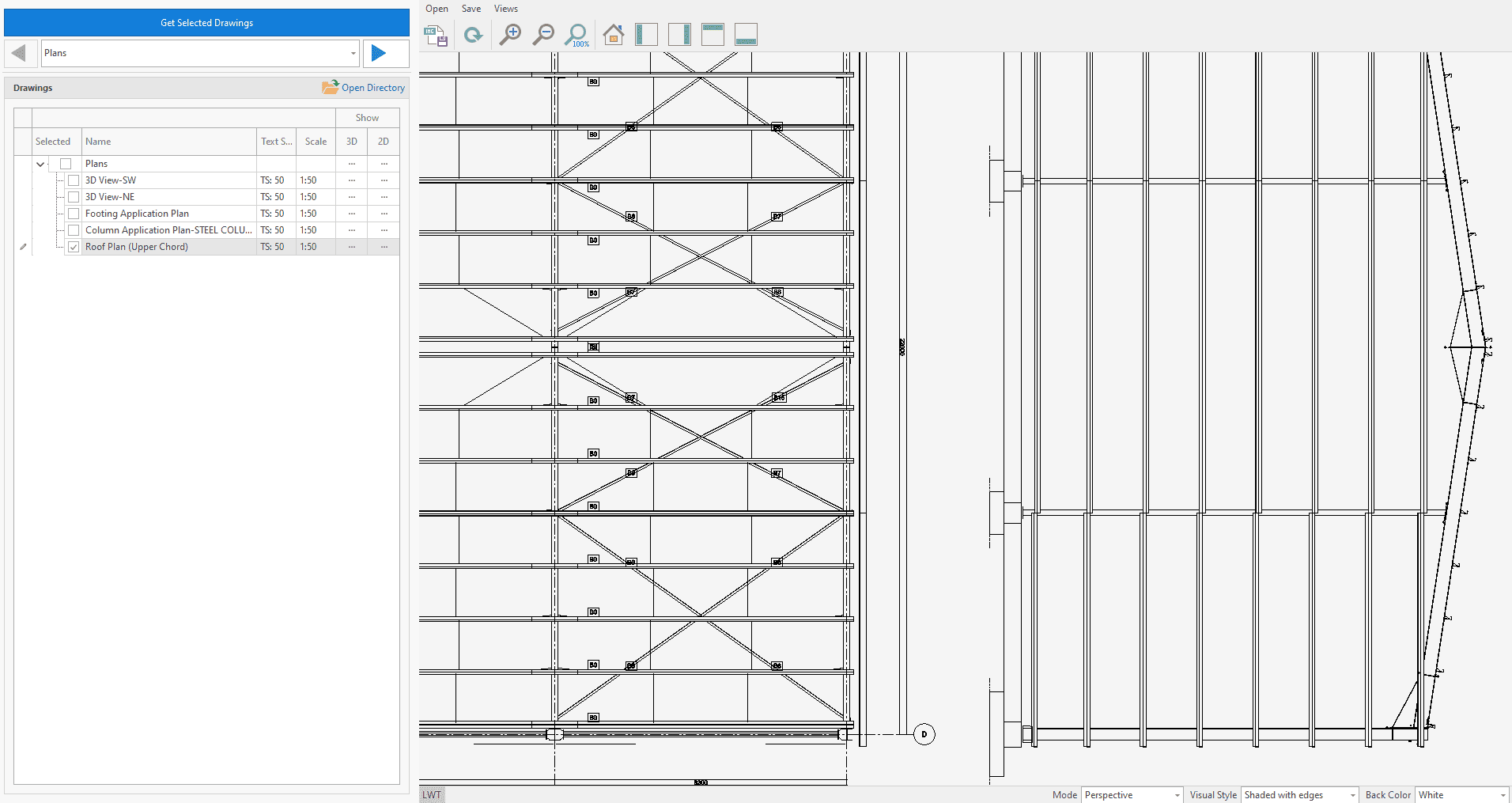
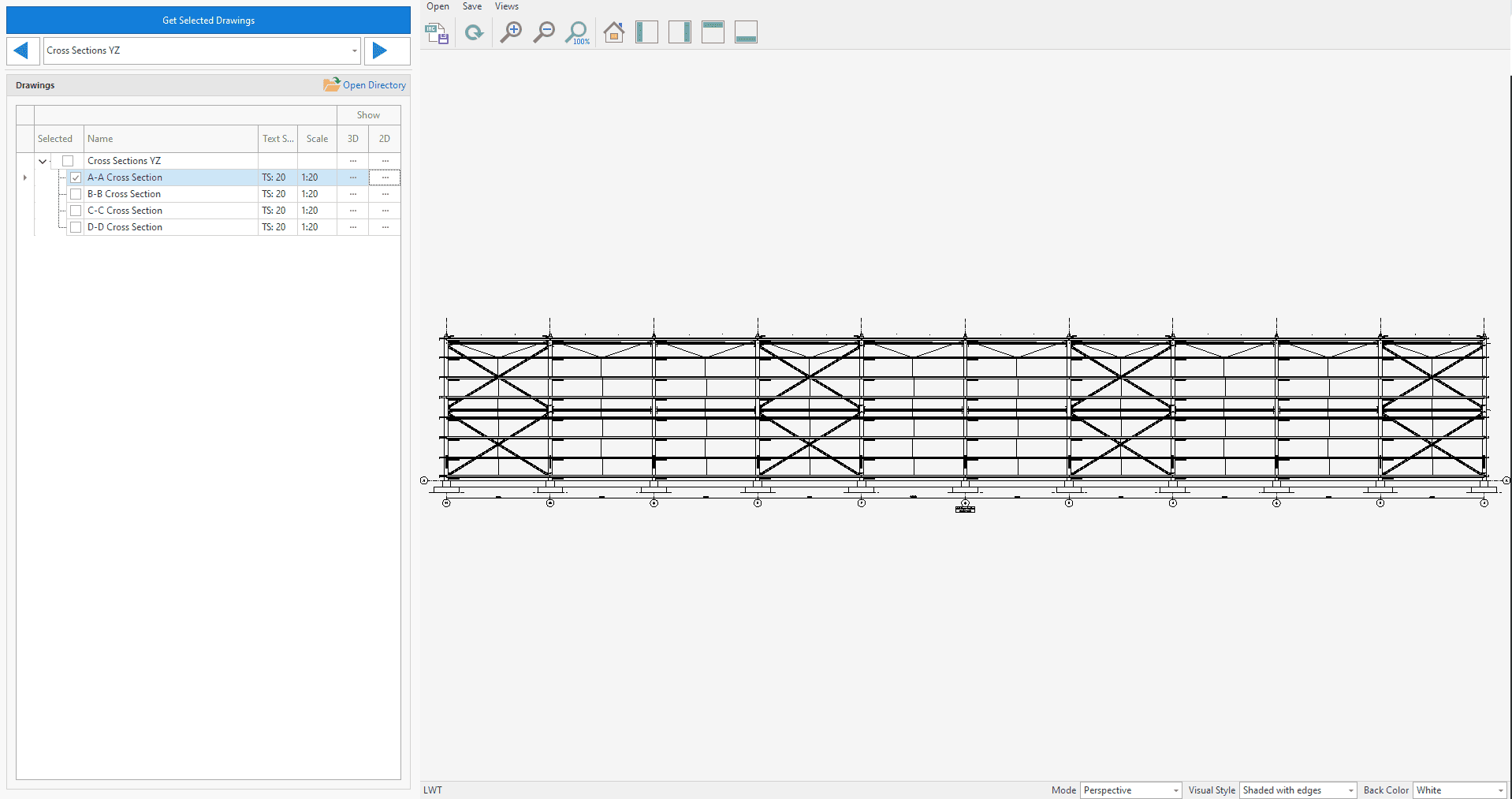
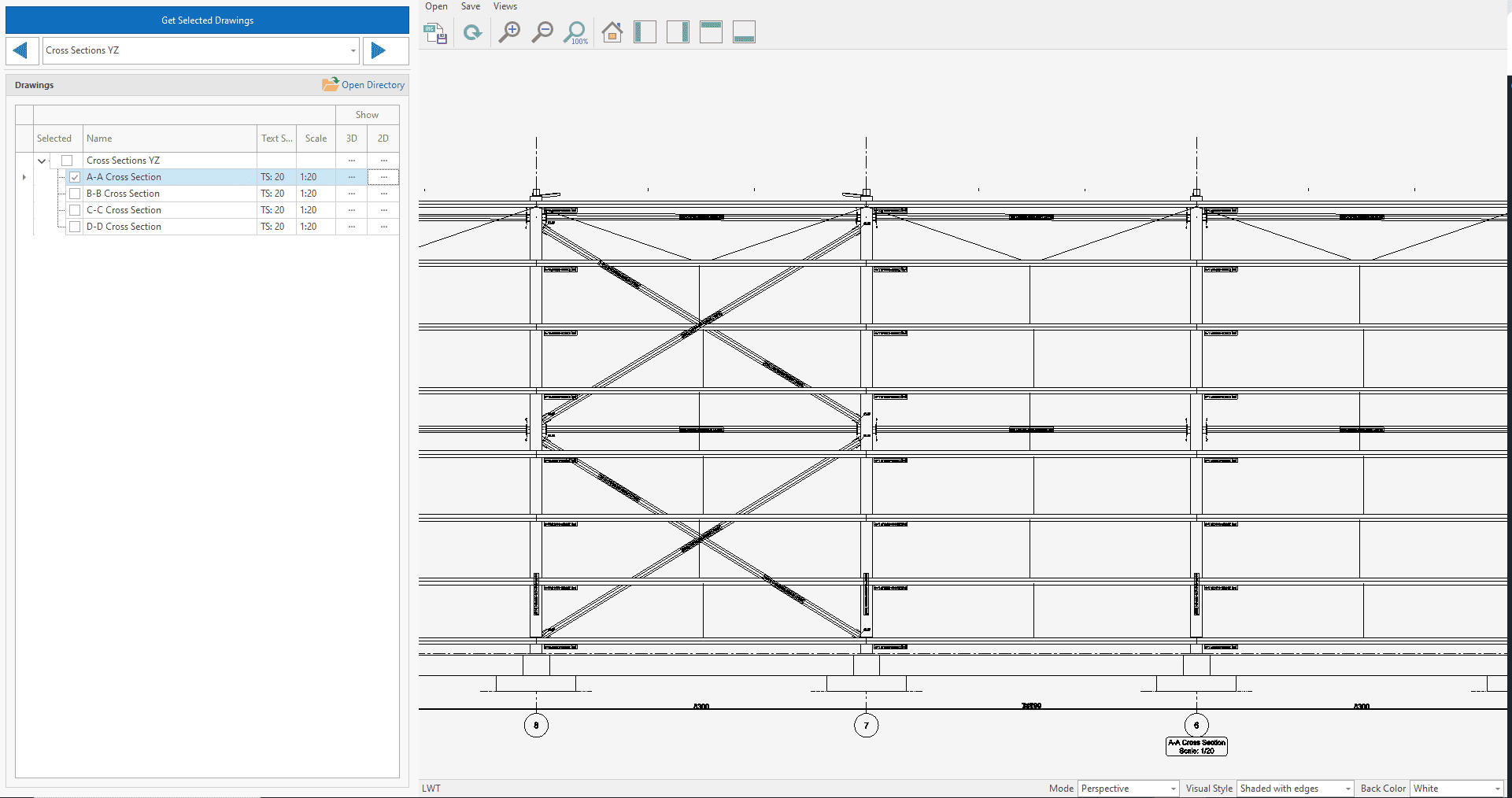
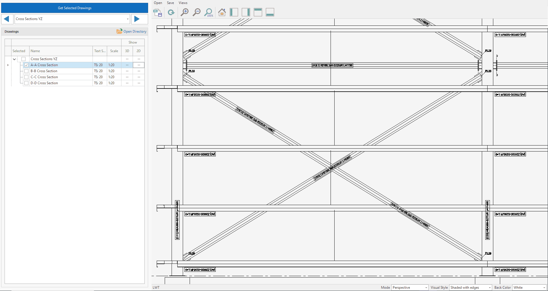
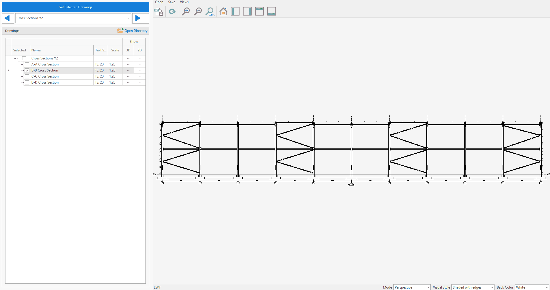
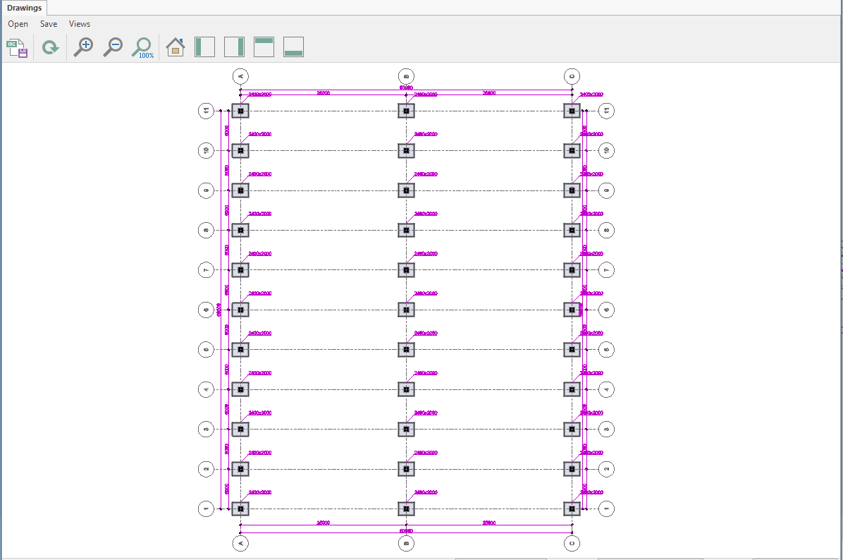
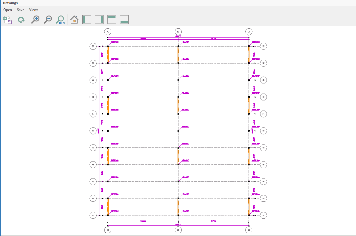
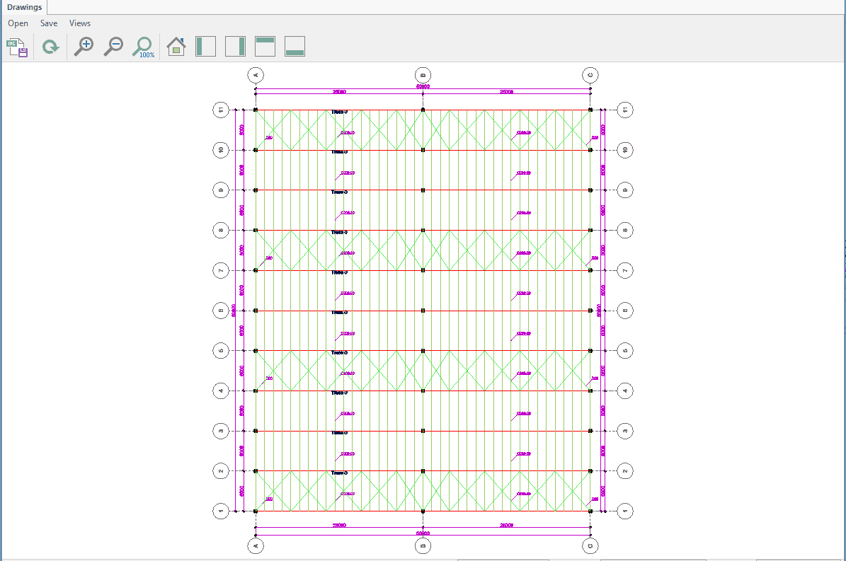
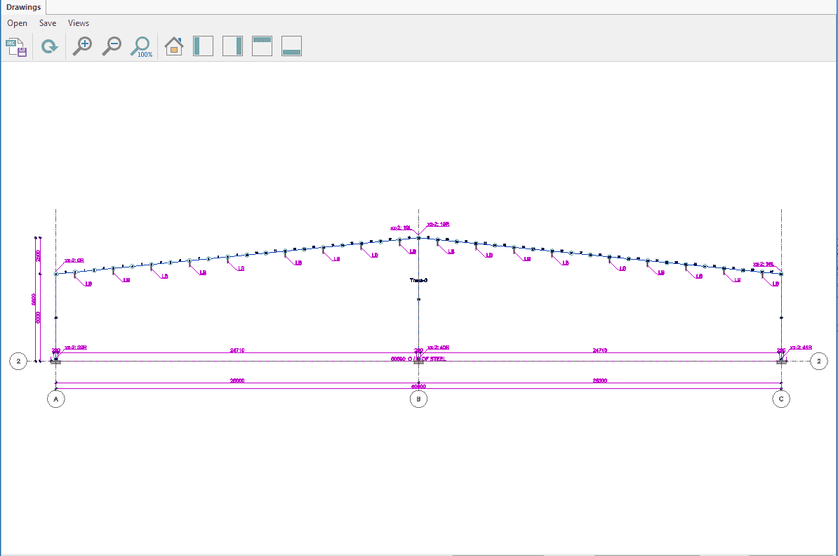
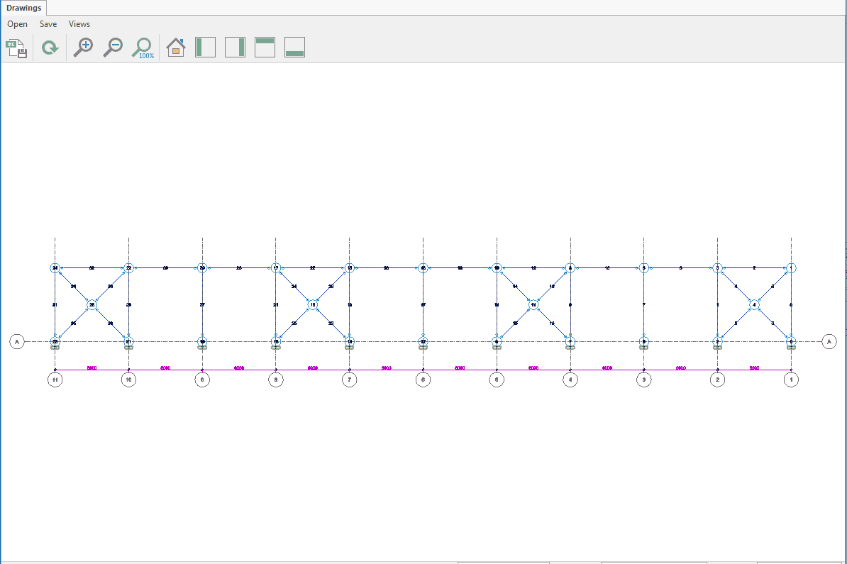
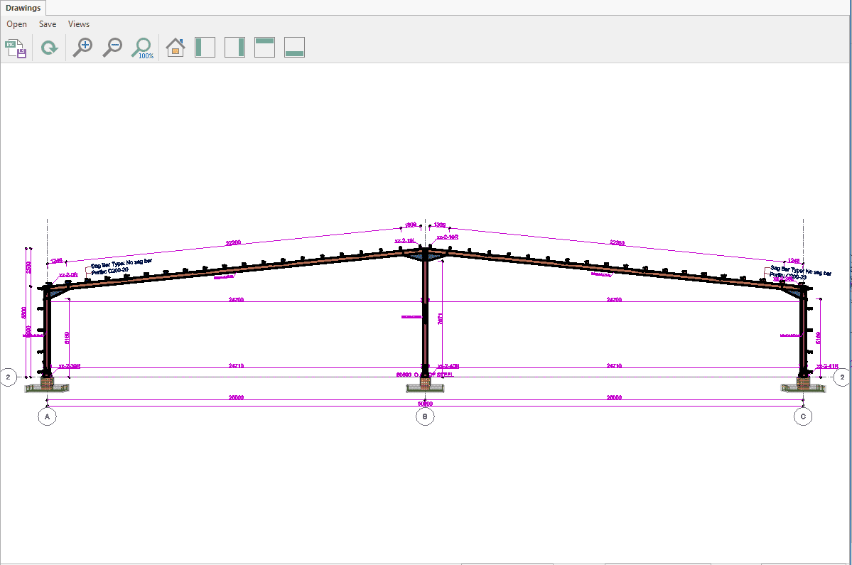
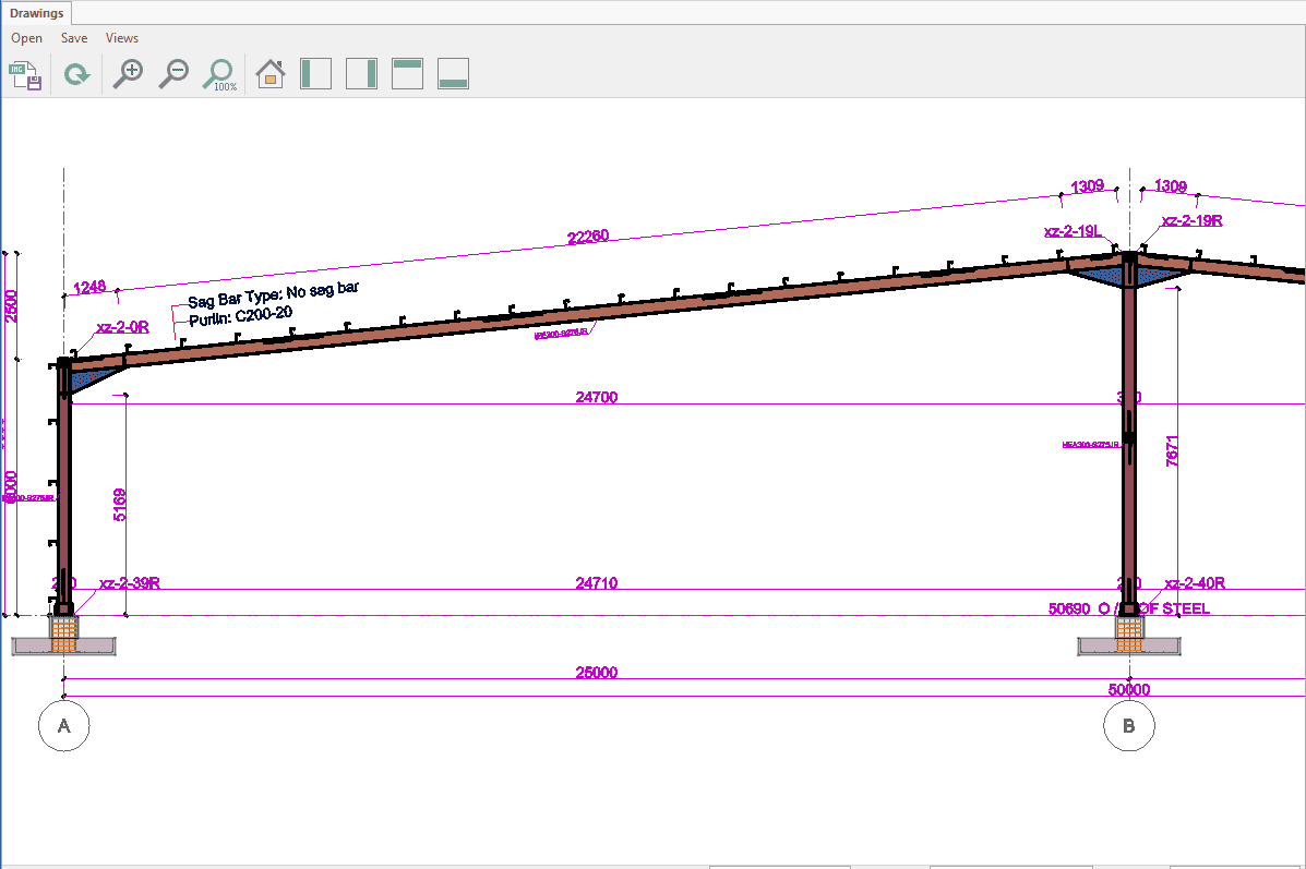
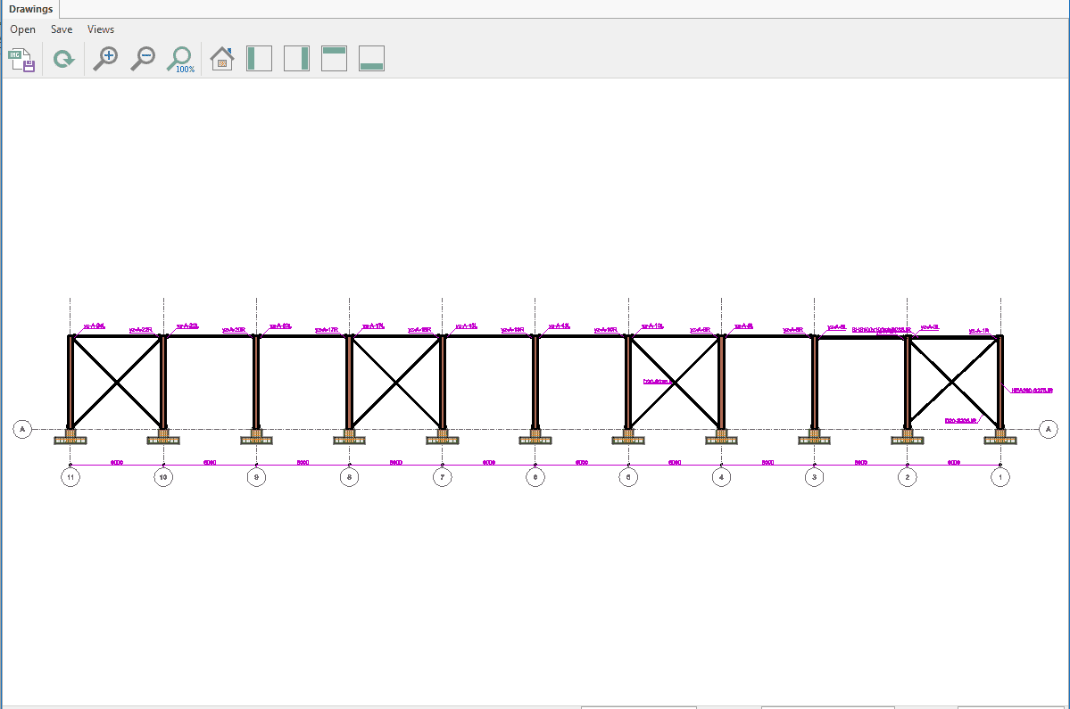
1- Sketches explaining the structural system.
2- Standards and regulations used in the design and other relevant document information
3- Load information based on the design (vertical fixed loads, live loads, roof loads, equipment loads, temperature change effect, snow and wind loads, soil thrusts and other loads.
4- Earthquake parameters for the design of the building under earthquake effect
5- Applied design method and related load combination coefficients
6- Characteristic strengths of material and bolt classes and weld metal strength information
7-Soil parameters considered in foundation design.
Analysis and dimensioning controls of the structural system, stability controls, joint and attachment details and their calculations will be given in detail, clearly and traceably in the project calculation report.